• Steel Soldiers now has a few new forums, read more about it at: New Munitions Forums!

  • Microsoft MSN, Live, Hotmail, Outlook email users may not be receiving emails. We are working to resolve this issue. Please add support@steelsoldiers.com to your trusted contacts.


H-161 Head Sets not working

Cdub

New member
1,082
2
0
Location
New Milford, NJ
Hey Guys,

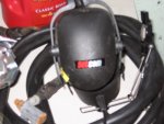
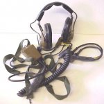
I've been really beating myself up over these head sets to find
that they don't work. I have tried three head sets to find that only
one of the three works the way it should.........Is this typical
of the H-161 head sets.....??

The one that does work is the only one I took out of a sealed bag. The
other two should be new from what I was told. They look very new
but don't work they way they should or not at all.

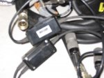
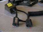
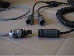
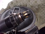
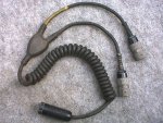
I have been trying to use the ' E ' and ' F ' models. The ' E ' model
has the nine volt battery type of connector and the ' F ' model has
the pin connector.

Has anyone else had these problems with the H-161 head sets.....??

Thanks,

C'dub
 

Attachments

  • Like
Reactions: art

Steamynachos

Member
178
3
18
Location
Calgary Alberta
Out of the last 12 sets I have used only 1 has worked well most problems are with the mic. or with the 9volt type connection not being just right most of the units I have used have been new in the bag it almost seems the longer they sit in the bag the more they deteriorate.
 

ida34

Well-known member
4,117
29
48
Location
Dexter, MI
Most of the trouble I have had has been with bad bailout connectors. A good connector and the headset works great.
 

OPCOM

Moderator
Steel Soldiers Supporter
3,657
27
48
Location
Dallas, Texas
If wiggling/pushing on/ the bailout does not reveal itmto be a problem, you can check the headset electrically.

I have not had any headset issues. mine are all "E" types. I've never taken one apart.. but you should be able to use an ohm meter to check.

I do not know which connector is which, but..

One connector (#1) will show 0 ohms betwen pins A and C when the switch is in the ICS position, and infinity in the OFF and RAD positions. This is the intercom command loop back to the VIC.

The other connector (#2) will show somewhere between 20 and 200 ohms between pins C and B when the switch is in RAD. Thisis the earphone.

At all times, there should be 20-200 ohms between A on the one connector (#1) and B on the other (#2), as this is a direct connection to the earphones. If you put it on, you should hear the faint or loud clicking caused by the ohm meter's test current when you measure this.

Use care measuring the mike, use a low current range. It should be between 20 and 100 ohms if it is a dynamic mike. The mike is connected between A and D on the other connector (#2), except when the switch is OFF. But you don't have a mike issue?...

As for the bailout connector, it is not clear from the diagram what is where.
 

Cdub

New member
1,082
2
0
Location
New Milford, NJ
At all times, there should be 20-200 ohms between A on the one connector (#1) and B on the other (#2), as this is a direct connection to the earphones. If you put it on, you should hear the faint or loud clicking caused by the ohm meter's test current when you measure this.
Hi PJ,

I set up the pins to be measured and I heard the clicking when I used the test leads and I measured 463 Ohms on the meter.......I used pin A on the long cable and pin B on the short cable.

Is that to far out of range.....??

Thanks,

C'dub
 

Attachments

Cdub

New member
1,082
2
0
Location
New Milford, NJ
One connector (#1) will show 0 ohms betwen pins A and C when the switch is in the ICS position, and infinity in the OFF and RAD positions. This is the intercom command loop back to the VIC.

The long cable is the intercom cable.........(1)

Between pins A and C measures 4.2 Ohms in the ICS position
Between pins A and C measures OL or infinity in the OFF and RAD positions


The other connector (#2) will show somewhere between 20 and 200 ohms between pins C and B when the switch is in RAD. This is the earphone.

The Short Cable is the Radio Cable.........(2)

Between pins C and B measures 466 Ohms when in the RAD position


At all times, there should be 20-200 ohms between A on the one connector (#1) and B on the other (#2), as this is a direct connection to the earphones. If you put it on, you should hear the faint or loud clicking caused by the ohm meter's test current when you measure this.
between A on the one connector (#1) and B on the other (#2) measures 466 Ohms and a clicking is heard in the headset


Use care measuring the mike, use a low current range. It should be between 20 and 100 ohms if it is a dynamic mike. The mike is connected between A and D on the other connector (#2), except when the switch is OFF. But you don't have a mike issue?...
Between pins A and D on the short #2 radio cable measures measures 149 Ohms in both the ICS and the RAD position.


PJ, I hope these readings will help in finding out why the head set is not working like it should..........So what do you think.....??

Thanks,

C'dub
 

doghead

4 Star General /Moderator
Staff member
Super Moderator
Steel Soldiers Supporter
26,247
1,168
113
Location
NY
Hey Cdub, I bought a pair of these headsets at the Gilbert show. They are SetCom brand, they have the correct plugs for the Vic-1 and work fine with mine. I just thought they looked close so I bought them. Anyone else have or use these?
 

Attachments

OPCOM

Moderator
Steel Soldiers Supporter
3,657
27
48
Location
Dallas, Texas
The long cable is the intercom cable.........(1)

Between pins A and C measures 4.2 Ohms in the ICS position
Between pins A and C measures OL or infinity in the OFF and RAD positions


The Short Cable is the Radio Cable.........(2)

Between pins C and B measures 466 Ohms when in the RAD position


between A on the one connector (#1) and B on the other (#2) measures 466 Ohms and a clicking is heard in the headset


Between pins A and D on the short #2 radio cable measures measures 149 Ohms in both the ICS and the RAD position.


PJ, I hope these readings will help in finding out why the head set is not working like it should..........So what do you think.....??

Thanks,

C'dub
I think it means the headset should work!! What exactly is wrong with it?

The measurements are not exact, 2x is OK, If you can hear clicking, you should/would hear sound when the thing is in at least one of the positions..

Bjorn, would you give an opinion on this? I don't see why it's not working.
 

Cdub

New member
1,082
2
0
Location
New Milford, NJ
Hi PJ,

My working head set tested the same except for the:

The long cable is the intercom cable.........(1)

Between pins A and C measures 4.2 Ohms in the ICS position
Between pins A and C measures OL or infinity in the OFF and RAD positions

which was giving me some kind of strange reading. The meter was jumping all over the scale and I coun't get the same readng twice.....?? and this is with the working head set.....hahah....go figure.....??

With the non-working head set. I can't hear anything through the ear phone but I do believe the mic is working. Then for some strange reason. I start hearing a loud side tone. Even in the ICS or RAD position. This is all happeninng when it's hooked up to the VIC-1 control box. I can't hear myself speaking in the ear phone like I can with the working head set.

Granted that the radio set and VIC have been tested with the working head set and a PRC-126 to talk back and fourth with.

I will try it all again hooked up to the VIC and see what happens.

Any ideas.......??

Thanks,

C'dub
 

Recovry4x4

LLM/Member 785
Super Moderator
Steel Soldiers Supporter
34,014
1,814
113
Location
GA Mountains
FWIW, I bought numerous sets of CUs new in the bag. All worked but the foam ear pieces in each one was deteriorated. I had one set that was much newer, maybe an EU? They were black and much better but the bottom line for me is the headsets are not very comfortable. Since going to the Powercoms, I've never looked back. I know this isn't any help with yours CW.
 

cranetruck

Moderator
Super Moderator
Steel Soldiers Supporter
10,350
74
48
Location
Meadows of Dan, Virginia
Keep in mind that when used with the VIC-1 system, there are some 30 connections that must be in perfect conditions for it all to function correctly, most if not all contacts are gold plated (including relay contacts). The accessible contacts may be carefully cleaned with a pencil eraser. Check the contacts on the C2298 box for example. BTW, the longer cable from the headset, marked with a yellow marking goes to the left hand connector.
The bail-out connectors are a problem and I ended up having a helper pushing them together while I taped them tightly to make a good connetion.....
 

Cdub

New member
1,082
2
0
Location
New Milford, NJ
Well as things truned out. I had a bad bail out cable. The seller sent me a hole nother headset which worked great except that the padding for the ear phones were falling apart. So I was able to use the new bail out cable with the old headset and she worked just fine.

Does anyone have a Bail out cable for the H-161 F model with the Nexus type connector they would be willing to part with.......?? This way I would have two working headset to use with the VIC-1 already set up in the five ton.

Thank You,

Craig
 

Attachments

Top
AdBlock Detected

We get it, advertisements are annoying!

Sure, ad-blocking software does a great job at blocking ads, but it also blocks useful features of our website like our supporting vendors. Their ads help keep Steel Soldiers going. Please consider disabling your ad blockers for the site. Thanks!

I've Disabled AdBlock
No Thanks