- 2,912
- 1,605
- 113
- Location
- Czech Republic
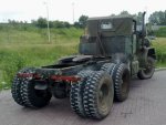
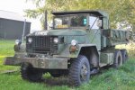
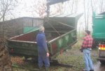
Dump to tractor conversion for dummies
I talked about this in other threads, but thought it would be a good idea to put all steps in one post, so people can easily look back at it as a reference on how to do this. I ended up with FIVE pages of text, a bit long for one post. Here are only the main points and the pictures. The full text with all explanations and problems that can occur can be downloaded from our website (link under the pictures)
Warning
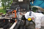
Trying to free these bolts might be problematic, be careful not to mess up your hands.
What you need to remove the dump bed
1. Spray can of WD 40 and a steel brush
2. Two bolt and nuts M10 - 8.8 high-grade steel. To bolt the dump bed to its subframe
3. Wrenches sizes 24, 26, and 29, best is the open-end-ring type. Get two of each.
4. Socket wrenches in 24, 26, 29.
5. Timber to lower the bed on: the pump which sticks out 10 inches below the unit.
6. A box to put in all your bolts, nuts, springs, rings, and whatever you took off and out.
7. A telescopic handler or crane able to manipulate at least 4,000 lbs at its tip.
Step one: 1-2 days BEFORE starting the real work.
8. Clean all bold and nuts and soak them in WD-40, which needs time to work.
Step two: make sure you have enough time and a good mood before you start.
Step three: the little things are easy to forget (with disastrous results)
9. Bolt the dump bed to the sub-frame.
10. Disconnect the levers to the hydraulic pump close to the pump.
11. Disconnect the pump from the drive shaft.
12. Tie the shaft with some rope or belt to the frame.
13. Disconnect the rear lights. They are connected to the sub-frame.
Step four: freeing the sub-frame with the bed in one go.
14. Front connection: remove the split pen out of the lower bolt.
15. Free the bolts and nuts.
16. Back connection: loosen the 4 bolts connecting subframe with the frame.
17. Take all bolts and nuts out and safe them in your box.
DO NOT DO THIS WITH THE DUMP BED RAISED BECAUSE IT SEEMS EASIER.
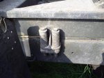
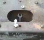
Left: the two spring-loaded bolts at the front.
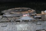
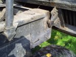
Right: rear connection with the four bolts in one line.
Step five: and now for the fun.
18. Connect four chains or heavy belts to the corners of the dump-bed
19. Raise the dump-bed unit SLOWLY an inch or so to get it loose from the main-frame
20. Check if all is really free, especially the connections to the hydraulic pump.
21. If not, lower the bed again and get it free.
22. If all is ok, raise the bed slowly, taking care not to damage the pump.
23. Use 4x4 timber to help maneuver the bed free
24. Lower the unit on the floor and make sure to keep the pump off the ground.
25. Take of the wooden spacer planks that was between the sub-frame and mainframe.

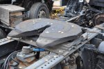
The white box in the pic on the right surrounds the hydraulic pump, showing the need for enough timber studs below the bed.
That is part one done. Time for one more cup of coffee for the road.
I talked about this in other threads, but thought it would be a good idea to put all steps in one post, so people can easily look back at it as a reference on how to do this. I ended up with FIVE pages of text, a bit long for one post. Here are only the main points and the pictures. The full text with all explanations and problems that can occur can be downloaded from our website (link under the pictures)
Warning
Trying to free these bolts might be problematic, be careful not to mess up your hands.
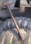
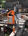
Sledge hammer with steel handle. Works perfect as lever for wrenches.
What you need to remove the dump bed
1. Spray can of WD 40 and a steel brush
2. Two bolt and nuts M10 - 8.8 high-grade steel. To bolt the dump bed to its subframe
3. Wrenches sizes 24, 26, and 29, best is the open-end-ring type. Get two of each.
4. Socket wrenches in 24, 26, 29.
5. Timber to lower the bed on: the pump which sticks out 10 inches below the unit.
6. A box to put in all your bolts, nuts, springs, rings, and whatever you took off and out.
7. A telescopic handler or crane able to manipulate at least 4,000 lbs at its tip.
Step one: 1-2 days BEFORE starting the real work.
8. Clean all bold and nuts and soak them in WD-40, which needs time to work.
Step two: make sure you have enough time and a good mood before you start.
Step three: the little things are easy to forget (with disastrous results)
9. Bolt the dump bed to the sub-frame.
10. Disconnect the levers to the hydraulic pump close to the pump.
11. Disconnect the pump from the drive shaft.
12. Tie the shaft with some rope or belt to the frame.
13. Disconnect the rear lights. They are connected to the sub-frame.
Step four: freeing the sub-frame with the bed in one go.
14. Front connection: remove the split pen out of the lower bolt.
15. Free the bolts and nuts.
16. Back connection: loosen the 4 bolts connecting subframe with the frame.
17. Take all bolts and nuts out and safe them in your box.
DO NOT DO THIS WITH THE DUMP BED RAISED BECAUSE IT SEEMS EASIER.


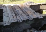
Left: the two spring-loaded bolts at the front.
Right: rear connection with the four bolts in one line.
Step five: and now for the fun.
18. Connect four chains or heavy belts to the corners of the dump-bed
19. Raise the dump-bed unit SLOWLY an inch or so to get it loose from the main-frame
20. Check if all is really free, especially the connections to the hydraulic pump.
21. If not, lower the bed again and get it free.
22. If all is ok, raise the bed slowly, taking care not to damage the pump.
23. Use 4x4 timber to help maneuver the bed free
24. Lower the unit on the floor and make sure to keep the pump off the ground.
25. Take of the wooden spacer planks that was between the sub-frame and mainframe.


The white box in the pic on the right surrounds the hydraulic pump, showing the need for enough timber studs below the bed.
That is part one done. Time for one more cup of coffee for the road.


