• Steel Soldiers now has a few new forums, read more about it at: New Munitions Forums!

  • Microsoft MSN, Live, Hotmail, Outlook email users may not be receiving emails. We are working to resolve this issue. Please add support@steelsoldiers.com to your trusted contacts.

M998 Was Alive, But Now Is Dead

Mogman

Moderator
Staff member
Moderator
Steel Soldiers Supporter
6,010
8,394
113
Location
Papalote, TX
What does the Protective Control Box (PCB) really protect? Seems they like to eat glow plugs.

Nothing smart about that, CAMO
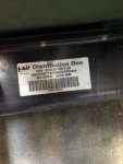
It was originally designed to protect the electrical system in the event the batteries were hooked up backwards, that entire premise was out the window as soon as the 200A alternator came out, no longer was the alternator going through and protected by the Protection Control Box.
It was a noble idea that was poorly implemented, unfortunately because of the military's pressure to make all items compatible from one model to the next the extreme short comings were never addressed, then you add some years and now modification by folks that because they will not take the time to research to the point they understand what is going on and I am not surprised that it is not a bigger issue than it is.
 

hawk-aggie

Member
59
33
18
Location
College Station, Texas
With the EESS out there will be no power to the run/start switch so it does not matter what position it is in. EESS is a much more appropriate term than "smart box"
If you had reviewed the TM, more specifically the schematic you would be aware of the power flow in the system, I would HIGHLY suggest you spend some time doing this, it will make the electrical operation of you vehicle much more clear to you.
EDIT actually Protective Control Box is the generic term but EESS is easier to type..
Thanks for the clarification about the power connections. I will try to work studying the schematics into my schedule.
 
Last edited:

papakb

Well-known member
2,288
1,186
113
Location
San Jose, Ca
Speaking of schematics, has anyone ever come across real, full schematics for any of the boxes? The manuals are only vague about them and the diagrams are only representative of the signals in and out of them. There's been a lot of reverse engineering done on the different models but I don't think I've ever seen a true schematic for them.

If anyone had them would you please post them here?

THANKS
 

hawk-aggie

Member
59
33
18
Location
College Station, Texas
Chapter 2 - Tan HMMWV

Different HMMWV, similar issue. Previously changed all the glow plugs - broke one tip off and had to remove the head to retrieve it, but that's another story. Been having some starting issues, but hadn't tried to start this thing for about a week or so. Decided to check all the glow plugs and install the aux grounding harness. Everything going well with the grounding harness until I got to the ground lug on the starter. The Army put some silicone sealant on the ground lug. Not a bad thing. I pulled the sealant off in one lump, and the ground wire that goes to the PCB came off as well. Oh, fiddlesticks. I knew right then and there the I had a sizable problem. Got that terminal fixed and connected the grounding harness at all 5 spots. Went to check the glow plugs - nothing, nada, zip. Checked my meter, and checked some glow plugs from the inventory. New glow plugs all read about 1.4 - 1.5. Pulled all the RH plugs and replaced them. Started to pull the LH plugs. They threaded out ,but wouldn't come out. So, I have ordered a glow plug extractor - don't know why I hadn't done that before. Now, we wait. In the meantime, I decided to remove the PCB and check inside it. What do I find? Toasted SCRs! BAM! However, this one might be repairable. It looks like only the two SCRs are toast (fingers crossed). I had one remaining "spare" PCB. Fortunately, it's the same model as the one that got toasted. Will be ready to try it once the LH glow plugs are replaced. I feel pretty good that everything will be ok, since I've checked all the grounding points and installed the new grounding harness. I'll report back on this one in about a week.

UPDATE:
HMMWV #2 is running again. Four glow plugs were very swollen. Checked everything and connected the batteries. Wait light stayed on 15-20 seconds. Was cold and took a bit to get started. Fired it up and let it set about 3 or 4 minutes. Voltmeter never came out of the yellow. Of course the engine had been sitting for about a week or so inside in the cold. Previously it surged for about a minute then went in the green. I figure I need to change the GPC - hopefully without breaking it off. Any thoughts or tips? Should I let it run longer to get warmed up? I don’t want to burn out another set of glow plugs, even though I’ve got about 60 new ones in the inventory.

ReplyLATEST UPDATE:
HMMWV #2 is running without incident. No voltage indicated on the dash voltmeter had nothing to do with the 200A generator. It was the - wait for it - PCB! Had inspected inside the one I installed to replace the fried one. Didn't see anything physically wrong. Suspect a disconnected a wire inside, since the vehicle operates otherwise like it should with the wait light pausing, etc. There wasn't any voltage indicated with a multimeter between the IGN point on the voltage regulator and ground, so the voltmeter on the dash wasn't reading anything either.

10/26/22 UPDATE:
Got the monster running and found a buyer!!!
 
Last edited:

hawk-aggie

Member
59
33
18
Location
College Station, Texas
Chapter 1 - Green HMMWV (continued)

This is the one that fried at least one PCB that we believe was caused by a faulty starter. Just received today, the kit to help us remove the broken starter bolt. Any way, I was installing a new windshield washer reservoir/pump. It came without one. I found that some numbskull connected the two wires that are supposed to be connected to the washer reservoir to each other under the dash. I've looked at the schematics, but couldn't tell if that could have been a contributing factor to the issues we've been having. Thoughts?
 
Last edited:

Mogman

Moderator
Staff member
Moderator
Steel Soldiers Supporter
6,010
8,394
113
Location
Papalote, TX
Chapter 2 - Tan HMMWV

Different HMMWV, similar issue. Previously changed all the glow plugs - broke one tip off and had to remove the head to retrieve it, but that's another story. Been having some starting issues, but hadn't tried to start this thing for about a week or so. Decided to check all the glow plugs and install the aux grounding harness. Everything going well with the grounding harness until I got to the ground lug on the starter. The Army put some silicone sealant on the ground lug. Not a bad thing. I pulled the sealant off in one lump, and the ground wire that goes to the PCB came off as well. Oh, fiddlesticks. I knew right then and there the I had a sizable problem. Got that terminal fixed and connected the grounding harness at all 5 spots. Went to check the glow plugs - nothing, nada, zip. Checked my meter, and checked some glow plugs from the inventory. New glow plugs all read about 1.4 - 1.5. Pulled all the RH plugs and replaced them. Started to pull the LH plugs. They threaded out ,but wouldn't come out. So, I have ordered a glow plug extractor - don't know why I hadn't done that before. Now, we wait. In the meantime, I decided to remove the PCB and check inside ti. What do I find? Toasted SCRs! BAM! However, this one might be repairable. It looks like only the two SCRs are toast (fingers crossed). I had one remaining "spare" PCB. Fortunately, it's the same model as the one that got toasted. Will be ready to try it once the LH glow plugs are replaced. I feel pretty good that everything will be ok,, since I've checked all the grounding points and installed the new grounding harness. I'll report back on this one in about a week.
Not really sure why the military thinks RTV is a good idea, instead of drying out afer getting wet it just festers underneath, unless of course YOU are the ONE that gets it completely sealed...
 

hawk-aggie

Member
59
33
18
Location
College Station, Texas
Speaking of PCBs... Have any of you ever seen and/or had experience with the brand? It has 3 cannon connectors - two in the engine bay and one under the dash. I think it was another effort to eliminate the GPC. The box is paired up with a Nartron GPC, but that shouldn't matter if the objective is to take the GPC out of the equation. Supposedly only for a 200A modification???
 

Attachments

Last edited:

Action

Well-known member
3,581
1,552
113
Location
East Tennessee
Those were very early use and burned trucks to the ground. The extra plug was just s separate glow plug harness. If you have this in a truck, replace it.
 

Action

Well-known member
3,581
1,552
113
Location
East Tennessee
You would replace the box / sender and the engine harness.
The 3rd plug is a glow plug harness. If you disconnect it, the glow plugs wont get hot.
 

Milcommoguy

Well-known member
Supporting Vendor
1,660
2,120
113
Location
Rosamond, CA
So, speaking of PCBs, has anyone designed a reliable substitute? I was reading an old thread where someone was about to go "live" with their design. Did that ever happen?
Yes. The CAMO BOX. Time and money are on the line to get it out. PM "milcommoguy" here to get on the list.

It's more than in the works and IT WORKS, CAMO
 
Last edited:

hawk-aggie

Member
59
33
18
Location
College Station, Texas
Repeat of above edit……

UPDATE: HMMWV #2 is running again. Four glow plugs were very swollen. Check everything and connected the batteries. Wait light stayed on 15-20 seconds. Was cold and took a bit to get started. Fired it up and let it set about 3 or 4 minutes. Voltmeter never came out of the yellow. Of course the engine had been sitting for about a week or so inside in the cold. Previously it surged for about a minute then went in the green. I figure I need to change the GPC - hopefully without breaking it off. Any thoughts or tips? Should I let it run longer to get warmed up? I don’t want to burn out another set of glow plugs, but I’ve got about 60 new ones in the inventory.
 
Last edited:

hawk-aggie

Member
59
33
18
Location
College Station, Texas
New update on HMMWV #2 - It's running, but the voltmeter stays in the yellow. Tested another GPC (just plugged it in while it laid on top of the engine - and, yes, I disconnected the batteries), but that wasn't the issue. Voltmeter still in the yellow. Connected multimeter to batteries while engine was running to rule out a bad voltmeter. No voltage change when revving the engine. A buddy of mine who's a mechanic in the National Guard says it sounds like the generator and not the PCB or GPC. It's a 200A model, so I changed the regulator before hauling that heavy monster out of the engine bay. Same result. Looks like the generator gets changed out next week.

No new progress on HMMWV #1. Trying to get #2 out of the building and parked in the compound.
 

Action

Well-known member
3,581
1,552
113
Location
East Tennessee
New update on HMMWV #2 - It's running, but the voltmeter stays in the yellow. Tested another GPC (just plugged it in while it laid on top of the engine - and, yes, I disconnected the batteries), but that wasn't the issue. Voltmeter still in the yellow. Connected multimeter to batteries while engine was running to rule out a bad voltmeter. No voltage change when revving the engine. A buddy of mine who's a mechanic in the National Guard says it sounds like the generator and not the PCB or GPC. It's a 200A model, so I changed the regulator before hauling that heavy monster out of the engine bay. Same result. Looks like the generator gets changed out next week.

No new progress on HMMWV #1. Trying to get #2 out of the building and parked in the compound.
You do know the the 200 amp takes 30 seconds or so after startup to start charging?
 

AAVP7

Well-known member
217
261
63
Location
Dortmund, Germany
Niehoff, who made most of the 200A alternators, have a very good troubleshooting guide on their website. Step by step. Takes the guesswork out of the parts-swapping.
I had a shot regulator on my 200A last year, and a Niehoff rep I talled to (very helpful fellows, by the way) said that most of the time it´s regulator failure. Failure of the alternator itself is said to be rare. In my case, the troubleshootig guide pointed to the regulator, and after swapping that, everything was fine again.
 
Top