• Steel Soldiers now has a few new forums, read more about it at: New Munitions Forums!

  • Microsoft MSN, Live, Hotmail, Outlook email users may not be receiving emails. We are working to resolve this issue. Please add support@steelsoldiers.com to your trusted contacts.

Manual CTIS, electric over pneumatic.

Ronmar

Well-known member
4,221
8,057
113
Location
Port angeles wa
Was asked to start a separate discussion and a manual ctis drawing. we already had a thread on it so I revived that with a current diagram. it is also in my videos on youtube linked in this discussion.

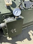
basically pin H is 24v. Pin R is control, pin B is inflate and pin C is deflate. You energize control to seal the system, and give a shot of inflate to pressurize the system and open the wheel valves… then you can continue to inflate or deflate. Opening control releases system pressure closing the wheel valves in a normal working system… You of course need a pressure gauge connected to the PCU pressure sensor port to measure tire pressure when the wheel valves are open…

IMG_3834.png
 

wandering neurons

Active member
250
118
43
Location
Fallon, NV
After fighting the CTIS for several years, I finally broke down and made my inflation system electric-over-pneumatic. Before the mod, I was getting:
Two steady lights during deflate cycle, the ECU would stop. I’d restart and after repeated cycles, would finally get one light on the desired setting.
Five simultaneous flashing lights. Went away after using dielectric grease on the ECU canon plug.
Five sequential flashing lights and flashing CTIS OVERSPEED. Holding HWY and EMER would not reset. Suspect failed controller, probably memory that stored settings.
Dead, done, stick a fork in it.
My design of the electrics was to use one single-throw momentary toggle for Control and the inflate/deflate is a on/off/on momentary toggle. Up is for check pressure/inflate, down is deflate. Pin H is 24v to the Control switch. Output of that switch goes to Pin R and also to the center terminal on the on/off/on switch. Positioning the on/off/on toggle up applies power to Pin B of the canon plug and down sends power to Pin C.
The ECU was totally gutted of all components, a plate made to replace the top mount switches. The pressure gauge mounts in that plate, the hose to the PCU is hidden behind the canon plug.The canon receptacle in the ECU had the four necessary pins pulled completely out and wires fed through the holes to push into the plug directly.
It works, I’m happy, job is complete.
 

Attachments

Top