• Steel Soldiers now has a few new forums, read more about it at: New Munitions Forums!

  • Microsoft MSN, Live, Hotmail, Outlook email users may not be receiving emails. We are working to resolve this issue. Please add support@steelsoldiers.com to your trusted contacts.

MEP-1050 3 Phase To Single Phase

BadAmish

Member
36
44
18
Location
Grants Pass, Oregon
Hello genset experts,

We got a MEP 1050 from GovPlanet that is 3three phase and recently we had a licensed electrician come out to give us an estimate on the cost of hooking it up to our home. He said we need to switch the MEP-1050 from three phase to single phase and I do not know how or even if this can be done. I sent him this thinking it was what he wanted but he told us it was not:
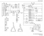
mep-1-50-generator-windings.png

I have another thread here called MEP-1050 Fault Code 3665 - https://steelsoldiers.com/threads/mep-1050-fault-code-3665.224125/ - where I am still trying to solve our fault code 3665, but there is other information there and photos in cxase it helps.

Thank you
 

Scoobyshep

Well-known member
1,368
2,127
113
Location
Florida
Of the drawing is accurate in the head being 12 lead it is absolutely possible. Problems I foresee are the monitoring circuits in the generator getting pissy.

Sent from my SM-S908U using Tapatalk
 

kloppk

Well-known member
Steel Soldiers Supporter
2,306
4,108
113
Location
Pepperell, Massachusetts
Looks like the DCS monitors the AC Voltage at K1-A1, K1-B1 & K1-C1 to monitor the gen head output voltage referred to as the GENSET Voltages.
I'd assume the DCS uses the GENSET Voltages as inputs to the AC Voltage Regulator system in the DCS.
The DCS also monitors the AC Voltages at the output lugs referred to as the BUS Voltages.


1754423304534.png

1754425465412.png

1754425605562.png
 
Last edited:

LuckeyD

Active member
78
240
33
Location
Vilseck, Germany
Good Day: Two members have it on the head of the nail. The monitoring circuits are looking for 3 phases and S12 is set for a 1050 which is a 3 phase machine.. You have 52 AMPS per phase on the 3 phase machine which if you use only 2 phases, you have your 120/240VAC with 52 AMPS each to neutral. The issue here is if you do not put a load of some kind on the unused phase you will be running unbalanced and this causes issues after a time. This one made me do the scratchy head trick and here is bit of knowledge few know. The MEP 1050 and the MEP 1040 : the only difference is one cylinder in the engine and the S501. Same monitoring with the exception of an S501 where the DELTA strapped main gen is monitored. Same main gen, same DCS, one cylinder in the engine more on the 1050, but I do not have in my head where to find what makes and monitors what as the S501 is rotated. I do not have a switch so I can not for certain say what to connect to what. You just set the S12 on the A2 card to say it is a MEP-1040 after making the main gen a DELTA with the 501 and the monitoring connected correctly as a 10KW. Then you have about 73 AMPS per phase at 120/240 and the DCS will say you are over loading the gen which is a matter of CT1-CT3 value change . Then the DCS will see a 120/240V connected and allow the gen to start. Other than removing the reconnect board and installing an S501 and wiring it up as a 1040 10KW I can't figure any other way because I do not have the info of how the S501 connects internally. A couple in the forum may be able to figure that one out but CT values must also change or use INPOWER AMMPS to change the values in the programming using a LAPTOP. Sorry, I am unable to come up with an exact answer as we were trying to keep them running as designed.
 
Top