• Steel Soldiers now has a few new forums, read more about it at: New Munitions Forums!

  • Microsoft MSN, Live, Hotmail, Outlook email users may not be receiving emails. We are working to resolve this issue. Please add support@steelsoldiers.com to your trusted contacts.


Electronic Parts Replacements Info for the MEP-802A

Daybreak

2 Star Admiral
Steel Soldiers Supporter
1,521
741
113
Location
Va
First I want to thank you for your valuable help and offering your knowledge on these generators, especially since you are taking away precious time from your family when doing so.

I understand the GI reason for cannibalizing parts when in the field, especially during combat.

The switch with the broken shaft is S6. I will try to replace S6 first and then S1 with the improved versions.
Unfortunately there are none on ebay at the moment. I am going back searching SS for past switch source info.

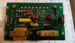
V5, the Varistor for the DC System, is at the bottom of the Resistor Bank, the itty-bitty red dot mounted on the ceramic white posts. (The original posts were snapped off).
I wonder what is used (V5) in the newer gen sets. Can anybody provide pictures, especially if there are product markings?
I am searching the web for +,- 75V MOV, possibly one capable of absorbing more energy than V5. If I can't find such a Varistor, I will replace it with a pair of 75V Si Avalanche diodes stacked back to back. There should be little difference loading wise to the circuit.

I was thinking of a new thread title called "Electronic Parts Replacements Info for the MEP-802A".
Now if I can find the instructions for setting up a new thread.

Any comments, especially if this info may be redundant and already exists elsewhere?
Howdy,
I will look at the control box I have and see if I can remove the whole assembly. I will compare it to my MEP-802A to see if they are the same.
 

Daybreak

2 Star Admiral
Steel Soldiers Supporter
1,521
741
113
Location
Va
Howdy,
OK, I have looked them over and they are all the same
control diodes and varistors.jpg

I also have MEP-802/803 panel components parts for sale here

But the Master Start Switch Kraus & Naimer Switch and Knob 5930-01-531-2976 88-22829 and the Rotary Selector Switch Kraus & Naimer Switch and Knob 5930-01-531-2977 88-22830 are both the blue plastic style.
 

kb3bf

Member
127
1
16
Location
Howard County Md.
It appears that even on newer models V5 is still too small to have any markings on it. I wonder who makes this "pea"?

I realize that I am looking for parts that most folks will never need unless their MEP was also raided.

I should be able to find the needed parts sooner or later, except the Freq. Trip Switch, unless there is another parts source.
I can't get the company to reply. They probably don't deal with the public directly.

The following is a source which I am using (see figure 21) for building S14 from a Texas Instruments Bulletin based on the LM2907N chip.
http://www.ti.com/lit/ds/symlink/lm2907-n.pdf
However 60Hz time constants need to be implemented in the circuit design. Not difficult to do for the average circuits buff.

When finished I'll post the details.

When I get the MEP to produce power, I will contact you for S6.

Many tnx for setting up this thread.
 

kb3bf

Member
127
1
16
Location
Howard County Md.
Ok I found out from the Parts TM that V5 is part number V68MA3B and MOUSER has it.

It is also meant to be a fuze, hence why it is so small. I'll scrap the idea of using 75V Avalanche diodes.

V5 problem solved, one step closer to get the rest of the needed replacement parts.
 

Daybreak

2 Star Admiral
Steel Soldiers Supporter
1,521
741
113
Location
Va
Howdy,
OK, either way, I have taken the diode panel out.
diode panel.jpg
 

kb3bf

Member
127
1
16
Location
Howard County Md.
I hope you did not clip all those leads!
It is a lot less work just to solder the missing V5 part, so I am getting them from MOUSER, they are less than 1$ each.
Might as well get 10.
 

Guyfang

Moderator
Staff member
Moderator
15,903
22,183
113
Location
Burgkunstadt, Germany
Now your cooking with gas! This is how to work the problem. I posted the part number in the other thread, but since you have it here, no need to redo the wheel. Lets see some more pictures of the set, and we can find out what is missing.

Good deal Mike!
 

kb3bf

Member
127
1
16
Location
Howard County Md.
This is a more appropriate thread!

YES, I was missing the parts manual info, but with that in hand I can proceed with the rest of the parts needed.
(In 42 years with the Army (civ) I hardly ever had to look at a TM manual, if you can believe that. I did mostly MIL STD 461, Antennas and RF/E&M).

You are right about those cold joints on the V5 terminals. I saw them after taking the images. I was in a hurry and the MEP was getting wet.
You may have noticed the wet spots too. I will be mounting new varistors soon on both gen sets.

After further checking V5, I realized I jumped to the conclusion they were used as fuzes. That's not so, Littelfuse is the name of the outfit that makes them.
An interesting name for a company making MOVs.
The issue with MOVs after absorbing energy spikes over time is they can degrade and may open up. There is no telling if they are still good or not . Only testing can determine that, but that's not practical. Pray that they still work.

One more question: how do I find out what are the S6 and S1 ceramic/metal replacements?

I'll take more pictures when it stops raining here in the Mid Atlantic States. We have had rain on and off for 5 days.
I need a wheat cropper to cut the grass before rabbits make nests in the field. It has happened before.

Cheers
 

kloppk

Well-known member
Steel Soldiers Supporter
1,976
3,071
113
Location
Pepperell, Massachusetts
Here is a source for K14 I found in my records. Not sure if you tried it yet.
Quantum Controls
Chanhassen , MN
1-952-361-3694
Ask for Wendy
Price is 75 dollars each
 

Guyfang

Moderator
Staff member
Moderator
15,903
22,183
113
Location
Burgkunstadt, Germany
I believe this is the new S-6 Part Number: 31907LW, NSN: 5930-01-531-2977
I believe this is the S-1 Part Number: 75902LV, NSN: 5930-01-531-2976

Have you downloaded all the manuals?

What kind of antennas? I spent a lot of time fixing the AMG, (Antenna Mast Group) during my time in PATRIOT.
 

kb3bf

Member
127
1
16
Location
Howard County Md.
Hi Kloppk,

You are the Man!
I don't know how you got through to QC, but I left a message and sent email and never got a reply.
I came to the conclusion they did not want to be bothered with one unit at a time or deal with the public.
I will try with the number you provided and see what happens. Did you have to buy one? I really did not want to build one if I did not have to.
many thanks for the info.
 

kb3bf

Member
127
1
16
Location
Howard County Md.
I will try to search the web for those switches and see what comes up.

We designed and built RF and microwave antennas (and sources) for several applications, including non-linear scattering where you generate IMDs and harmonics off targets. When combined with conventional RADAR data you get more info about the target properties. We also made sure we weren't screwing up our own equipment so there was lots of EMI suppression. Do you remember a Lab called Harry Diamond Labs (HDL)? Great place to have been associated with, but mostly unknown to the public at large. It was often referred to as the "Harry-Who-Labs"? It later became the Army Research Lab. There are now several locations across the country.
 

kloppk

Well-known member
Steel Soldiers Supporter
1,976
3,071
113
Location
Pepperell, Massachusetts
Hi Kloppk,
... Did you have to buy one? ...

kb3bf,

No I didn't need to buy one. Fortunately my 802 was complete except for S1.
The info I posted was info I gleaned from a post a few years back and kept a copy of it for reference.


Does S12 get removed from the MEP if a remote start-up is used?
The MEP-802A doesn't have a "S12".
Did you mean S1?
With the remote start setup I came up with S1 is not removed or altered. Wires from the remote start relay contacts are wired to various S1 terminals as well terminals on S5 & S7.
 
Last edited:

kb3bf

Member
127
1
16
Location
Howard County Md.
kb3bf,

No I didn't need to buy one. Fortunately my 802 was complete except for S1.
The info I posted was info I gleaned from a post a few years back and kept a copy of it for reference.


The MEP-802A doesn't have a "S12".
Did you mean S1?
With the remote start setup I came up with S1 is not removed or altered. Wires from the remote start relay contacts are wired to various S1 terminals as well terminals on S5 & S7.
Sorry I meant S14, the Freq Trip Switch.
I saw an image where a remote starter circuit was wired to a MEP-802A and S14 was removed. Wires were added to the socket of S14.
I want to know if in this case S14 is no longer needed.
 

kloppk

Well-known member
Steel Soldiers Supporter
1,976
3,071
113
Location
Pepperell, Massachusetts
Did you choose to keep S14 with your remote autostart?
Yes - I kept S14 in my 802.

The only modification to the 802 from it's original wired configuration was to cut the wire between S5-3 and S7 and connected the two leads to the Normally Close contacts of a relay. This was done so that my autostart system could automatically open the 802's contactor during the automated shutdown sequence.
The other relays contacts in my autostart system are wired across terminal pairs of S1 & S5 to mimic the activiation of those switches during priming, preheat, startup, running, power output and shutdown. It uses 6 relays in total to independently control the following:
Preheat, Start, Run, Contactor Close, Aux Fuel, Contactor Open
.
 
Last edited:

kb3bf

Member
127
1
16
Location
Howard County Md.
I decided to check out the AC voltage regulator (Rev G) in my second MEP-802A since it was disconnected wire wise when I first got it.
While it was not one of the items that were removed, it remained mounted with only a pair of (loose) screws.
Because of this I was not sure if it had been deemed defective or not.

The FETS are the older MRF 450s and check out OK, same thing with the 1N5406 quad diode bridge, whose AC input is connected to pins 7,8.

However what I noticed was that the thermal compound for the heat sinks is totally dry and the dielectric pads had small tears. The former issue is due to the age of the generator (1994), and the latter I believe due to excessive screw torquing. The bottom line is there may be poor thermal transfer and possible dielectric breakdown.
So I replaced the pads and added new thermal compound.

Enclosed are some of the images taken. The good news is that most of the components in the AC voltage regulator can be fixed if any were fail. The only pain is that there is a lot of protective film coating which must be scraped away when doing any soldering.
 

Attachments

Top
AdBlock Detected

We get it, advertisements are annoying!

Sure, ad-blocking software does a great job at blocking ads, but it also blocks useful features of our website like our supporting vendors. Their ads help keep Steel Soldiers going. Please consider disabling your ad blockers for the site. Thanks!

I've Disabled AdBlock
No Thanks