• Steel Soldiers now has a few new forums, read more about it at: New Munitions Forums!

  • Microsoft MSN, Live, Hotmail, Outlook email users may not be receiving emails. We are working to resolve this issue. Please add support@steelsoldiers.com to your trusted contacts.


Help me identify these wires

Josephml21

Member
75
44
18
Location
PA
IMG_20190404_200120.jpgIMG_20190404_200102.jpg

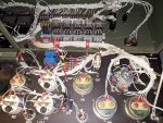
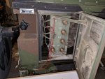
My mep-803a was delivered today. After cleaning it up a little and doing a inspection I came across these guys. I've never seen them on a unit before.

I put it on casters and installed new AGM batteries. It started right up and ran perfectly. Only had a chance to check the convenience outlets I will be doing fluids and filters tomorrow and then putting a full load on her.

Any ideas on the two random red wires running from the load panel up to the control panel? They are not attached to anything.

Any help would be appreciated,

Joe
 

Guyfang

Moderator
Staff member
Moderator
15,938
22,274
113
Location
Burgkunstadt, Germany
Just pull them out. Don't worry about them. To leave them hanging like that is an invitation to disaster. The wires below, could touch an output terminal. The other end, could touch metal in the control cube. Now wouldn't that be fun!

I once got shocked by all three phases, because of a stupid act just like this. Some fool cut a cable off, but left it hanging down. The other end, he had removed from the buss bar, and laid it off to the side. Naturally, it fell back in place. All three phases. Ten meters away, I reached into a poorly lit control box, and the wires dangling down ran across the back of my hand. I was not happy. He wasn't happy, after I shook him all over the control room. Stupid, stupid, stupid.
 

Josephml21

Member
75
44
18
Location
PA
Sounds good guy, do you have any clue what they were used for? When i picked up the set it looked like it was getting normal usage. Wires were still attached to the load lugs and the exhaust cover was removed but included with the unit.
 

Light in the Dark

Well-known member
Steel Soldiers Supporter
3,583
5,177
113
Location
MA
Yeah those werent there from the factory, remove them. The military has many custom things they do with equipment as the need calls for.
 

Guyfang

Moderator
Staff member
Moderator
15,938
22,274
113
Location
Burgkunstadt, Germany
Have you measured at the 120 volt outlets? And your meters work? In all voltage configurations? It looks shade tree to me. Nothing like any Army extras. The only reason I would want to bring VAC back into the control cube is? No. Why? I can not think of a reason at all. There are already circuits that would provide that voltage. No reason to have/make another VAC path back to the control cube. You could, although its not how I would do it, but you could excite the main gen that way. Run 24 volts to the main gen to excite it, if for instance the S1 didn't work right, or for some reason the wiring to initially excite the F1 and F2 wasn't there. Complicated, unwieldy, and dangerous. But possible. Lots of people have read the old story about exciting a main gen by hooking some batteries together and poking the two wires into the 120 volt outlet, to accomplish excitation. It works, but I would never in my life poke two wires into the outlet that MIGHT have 120 VAC on it. Interesting.

Edit:

The Tobyhanna MWO. This could have been the route for the Aux. fuel tank gauge wires. But in no way, shape, fashion or form, should the wires have been hooked to the load output terminals. Below is taken from the MWO book.

4. A hole has been drilled in the generator to allow the auxiliary fuel tank gauge to be used. Size is 5/8”. The hole connects the Control Panel Assembly compartment to the Load Output Terminal Board compartment. A rubber grommet is installed around the hole to prevent damage to the cable that runs from the aux fuel tank to the control panel harness. See Figure 8 for location of hole.

View attachment Scan_0001.pdf
 
Last edited:

Josephml21

Member
75
44
18
Location
PA
I'm doing fluids and filters right now. Once I'm done I'll get out the multimeter and take some measurements.

The unit came from the Chambersburg auction site and I believe it was in use. Service wires were connected to the load lugs still and rather than disconnecting them there were just cut at the wire sock. Additionally they had the exhaust cover off as if they were using an extended exhaust pipe because the cover and hinge was in the accessories box in new condition.
 

Ray70

Well-known member
2,387
5,135
113
Location
West greenwich/RI
I've had several machines with a "Factory" installed ( if you want to call it that ) remote monitoring system that goes in place of the diagnostic connector.
It connects to the gages and shut off switch, but not the output lugs. I assume it was used to remotely monitor and shut down the generator. I wonder if you have the remnants of a " home made" type of similar hard wired remote system? Either way, remove it all and be done with it.
 

Josephml21

Member
75
44
18
Location
PA
I removed them and went through all configurations and tested power at the lugs and everything checks out. This unit still had the standard diagnostic plug so it just kinds threw me through a loop. Thanks for the help everyone!
 

smokem joe

Active member
500
66
28
Location
Green OH
That sure looks like the remnants of a Tobyhanna mod like Guy said. I have had several units with the mod and they all had the wires there.
 

Josephml21

Member
75
44
18
Location
PA
I took the electrical tape off the wire that is connected to the emergency switch and it was fine, not frayed, cut or spliced. I just removed the two extra red wires.

Tested the unit and it run fine and makes power as it should on all configurations.

I still have the regular diagnostic socket, I believe it was just for a remote emergency stop switch.
 

smokem joe

Active member
500
66
28
Location
Green OH
They removed the rest of the remote system before sale. Technically it is still classified so all the remote systems should have been removed before sale. I have had a couple units that were partially removed and several with the system still intact. Every one of them had those two wires there. Some were cut off just inside control panel and some were longer like yours. I think every one of them had the extra looped as shown in your picture down on the main lugs.

Glad you got a runner! I previewed dozens at the auction when GL still had the contract. A lot of the Tobyhanna units had locked up engines
 

Josephml21

Member
75
44
18
Location
PA
Good to know! In the auction ad they showed it running but we all know it's still a craps shoot.

Today consisted of fresh fuel and injector cleaner, water fuel separator (that was fun like everyone elses pictures to follow) new oil filter and fresh T6 oil with some motorkote hyper lube. Cooling system flush and then topped off with peak global charge 50/50 antifreeze.

Oil pressure is just a smudge above 40psi and she's running well. Now I need to dig a trench, run conduit, pour a pad and start wiring her up.

Then inspection and I'm done.

Had to call it a day... I had plans for the evening.... IMG_20190405_190509.jpg
 

jamawieb

Well-known member
1,413
514
113
Location
Ripley/TN
Those wires hook into the emergency stop switch and were a remote shut off for a specific purpose. Usually for a mobile sateillate system.
 

smokem joe

Active member
500
66
28
Location
Green OH
I've had that exact same setup with a tobyhanna remote partially disassembled for sure. I may still have pics of it. They probably have the same wiring for more than one use then. I've torn that wiring out at least a couple dozen times. Looking at the first picture I'm not sure that would reach the stop switch. They usually leave a little slack and wire things in neater than pulling the wire tightly straight. Regardless of what it was for at least it's gone and it's a runner!
 
Top