• Steel Soldiers now has a few new forums, read more about it at: New Munitions Forums!

  • Microsoft MSN, Live, Hotmail, Outlook email users may not be receiving emails. We are working to resolve this issue. Please add support@steelsoldiers.com to your trusted contacts.


5.9 Cummins, NV4500, Hydro-boost, and Disc Brakes

mudguppy

New member
1,587
15
0
Location
duncan, sc
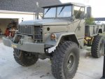
The following is the result of a week of vacation and the last few weekends, preceded by almost a year of research and planning.

Day 1 – Trans and Engine Pull

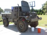
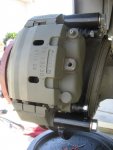
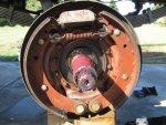
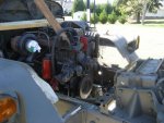
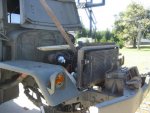
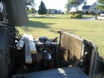
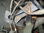
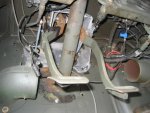
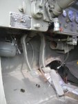
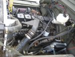
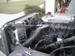
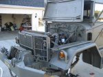
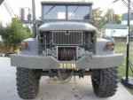
I originally would have started the afternoon before, but that never goes as planned. So first thing in the morning of now Day 1, I take a bunch of pics to document what went where before it never goes there again. Then begins the tear-down. The list of ‘Items to be removed’ is pretty extensive, as there isn’t much that will be retained in the power and braking department.

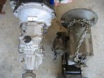
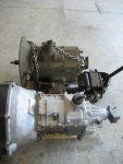
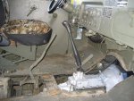
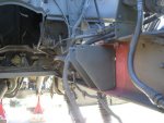
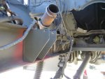
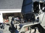
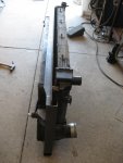
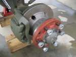
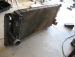
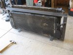
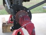
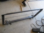
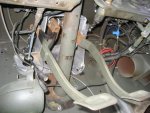
The trans was a bit fussy getting it fully extracted from the clutch, but came out none the worse for wear. Dropped it to the ground with PTO attached. Once the trans was out and rolling around on the floor jack, as expected, it really is hardly any larger than the NV4500 going back in its spot. Also removed at this time: PTO shift linkage, air pack, brake master cylinder, brake and clutch pedals. Now it’s on to the engine and known associates. Standard SOP for draining coolant, disconnecting lines and wires, and removing extremities such as air cleaner, exhaust piping, power steering pump, radiator, etc.

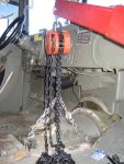
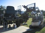
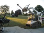
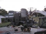
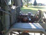
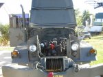
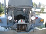
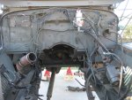
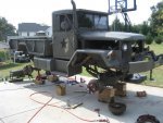
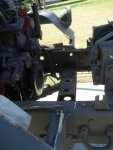
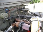
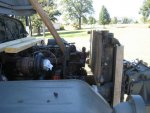
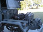
It’s good to know people: my neighbor has a tracked ‘Cat that was instrumental in pulling the multifuel out. Without help from him (and his machine), the engine would not have come out at such an installed height – lifting equipment is a must. Even w/ the ‘Cat, it didn’t want to come without a fuss. It took a good bit of connect/reconnect to get the angle correct for the front engine mount to clear the winch. Once this was cleared, backing it out of the truck was a little hairy – at one point, the ‘Cat was on its front (and final) roller, almost re-depositing the engine back in the truck. This would have been quite counter-productive. But it came out without actual incident.

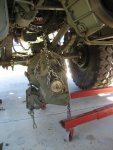
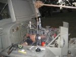
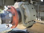
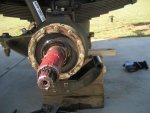
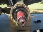
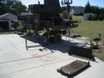
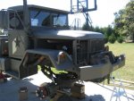
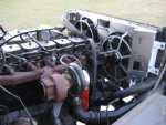
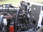
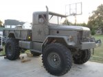
While I had it (and help), the ‘Cat was used to greatly simplify pulling the wheels/tires and lowering the truck onto blocks for the rest of the work to be done. Once that was done I realized there was still a little bit of day light, so we chained up the awaiting Cummins and trans and slid ‘er in to see what fitment would look like. This allowed me to mark where the motor and trans mounts would be located. We also identified a few clearancing opportunities. Not bad for Day 1.
 

Attachments

Last edited:

mudguppy

New member
1,587
15
0
Location
duncan, sc
Day 2 – Cummins and Trans Install

The first half of this day was committed to making room and shedding excess intricacies. The OE fuel system, much of the wiring, and other bracketry were removed. Then came the rivets. I knew they were there from measure a couple weeks ahead; at about mid-length of the engine, there are two small lengths of angle iron that are riveted to the inside bottom of the frame rail. There is at least one other pair of these in the rear frame of the truck as well. The best I can tell, these serve no functional purpose whatsoever. But because it’s me, these two pieces of angle are exactly where my new motor mounts needed to go. It took two hours to remove these 8” long pieces of angle that used 7 rivets. I actually didn’t/couldn’t get 3 rivets out – I just ground them flush.

By the afternoon, I was ready to set the motor and trans and bolt them in. Now, in the weeks coming, I have been measuring and measuring and cutting steel to make the new mounts. Then I’d measure, and I’d draw what they would look like, and measure some more. All the while knowing, and even saying out loud, that I would not weld up the new motor mounts before mocking the motor in the truck first; that way I could make last minute adjustments before final welding. Well, I built them the week before. So, with the marks from last night’s pre-mock-up, I drilled the frame and bolted the motor mounts in. I called my neighbor, we fired up the ‘Cat, and began fitting the engine and trans. When we finally got it aligned with the motor mounts, we wiggled, we jiggled, and we shook, and the engine dropped right into the mounts. My neighbor was astounded that it fit so perfectly; and I maintained a cool, confident composure that masked shear exuberance and awe that it actually fit, let alone fit perfect. This day ended on a high-note.
 

Attachments

Last edited:

mudguppy

New member
1,587
15
0
Location
duncan, sc
Day 3 – Begin the brakes

I knew this would be a long, but crucial day. I had always desired to rid the single circuit drums with some heavy duty hydro-boosted discs. I had been working with Steve Gerstner of Differential Engineering for quite some time. Steve has been offering the highest quality disc brake kits for Rockwell axles for 8 years now, but they have not been of sufficient capacity for a full-sized deuce until very recently. The plan was to utilize his new bolt-on heavy duty front kit and his weld-on heavy duty rear kit. While ordering the kits and making a work plan for the install week, I inquired about what exactly I would need to remove for the rear install. The standard offering is a weld-on bracket that clamps onto either the square or round part of the axle housing, depending on if your hubs are flipped in or out. Since I am running my hubs out, I asked why he didn’t make a bracket that bolts onto the OE brake backing flange. Well, he does now – mine’s the first. So now the brakes are a true bolt-on kit.

The fronts went on very simple and without fuss – remove brakes, removing backing plate, remove studs and replace with bolts. Bolt on new top and bottom plates/caliper brackets, install new hub/rotor assy, and bolt on caliper.

The rears are about the same except the brake backing plates are riveted on. It was at this time that I realized that the designers/builders of the truck really weren’t all that great of engineers. I’m serious. Anyway, that took a long time to get the rivets ground off and the plate removed. I ended up having to drill the centers out of all 24 rivets in order to get them pounded out. You can’t use a torch because you run the risk of work-hardening the brake flange – if you do this, you can’t drill out the 3/8” holes for the 7/16” bolts for the new brackets.

The rotors are 15” diameter and vented and the calipers are F550 rears – same at all 4 corners. The kits come with everything you need – all hardware and even two special races for the front hubs. And if you get more than one kit (like me), then Steve throws in the machined hubs and assembles everything at no additional charge. You can’t be that with a stick.
 

Attachments

Last edited:

mudguppy

New member
1,587
15
0
Location
duncan, sc
Day 4 – Finish the brakes / Radiator and IC support

Because of all the fun I had with the rivets, I only got one rear done the day before, so the first half of this day was spent finishing the rear brake. The second half was committed to fabricating the support that I would need to mount the Dodge radiator and intercooler. I had done a lot of measuring prior to this and even more during removal from the donor Dodge. This let me design the new support prior to the engine swap project. I didn’t fabricate it ahead of time – mainly because I ran out of time. This support frame bolts the stock radiator and intercooler utilizing the OEM bushings.
 

Attachments

Last edited:

mudguppy

New member
1,587
15
0
Location
duncan, sc
Day 5 – Fitting the radiator and IC

Now that I have a frame to hold these components, I can see how it will fit under the hood. I was confident that it would fit under the hood from measuring previously. I knew that the headlights would have to be ejected from the area and reinstalled somehow (more on that later). What I didn’t realize is how nice of a fit it would be. I ended up having to trim the inner fenders to make room for the IC inlet/outlet and boots – honestly, I could have gotten away with less trimming. Regardless, I am going to make something to close the gap and to prevent excessive mud thrown through the opening.

Getting the support frame, radiator, and IC in and bolted down was pretty easy. Getting it rigid, well, that’s another story – the OE radiator is held sturdy from the engine and I won’t have this luxury. I was starting to panic when I realized there was a stupid-simple solution: the OE bars/brackets used to support the headlight inner panels could be easily modified. So with a little straightening and re-bending time with the bench vice and hammer and a 90° twist, re-drill, and voila – rock solid support for both the radiator/IC support and the front grill.
 

Attachments

Last edited:

mudguppy

New member
1,587
15
0
Location
duncan, sc
Day 6 – Hydro-boost and Pedals

I knew this would take all day. I knew it would suck. I was right on both accounts. I had planned from the beginning to take the pedal support and pedals from the donor Dodge and ‘somehow’ fit it under the dash of the deuce. I also knew I wanted to use all Ford Superduty brake parts. Again, the Ford brake booster would ‘somehow’ mate to the Dodge pedal support. Well, it wasn’t that bad, but it wasn’t easy. The bolt patterns between the Dodge and Ford brake boosters were different… as in, not even close. I ended up making cardboard templates of both and used it to re-drill the pedal support. I got 3 out of 4 brake booster bolts through the pedal support by angling the brake booster by about 10-15°. There was a void where at the 4th bolt location, so a ¼” backing plate was made – this also made up the elevation difference across the stupid ribs that are pressed into the firewall. Stupid designers.

Drill out some holes in the firewall for the brake booster push-rod diaphragm and clutch master cylinder and mount it all up. Sounds easy, took all day.
 

Attachments

Last edited:

mudguppy

New member
1,587
15
0
Location
duncan, sc
Day 7 – Hydraulics and hydraulic reservoir

With the brake booster mounted, I could now determine where the reservoir would/could go. I used a reservoir from an old Ford tractor – this is basically a canister design, so one side is completely open. I used some 16ga steel and 1” angle to seal the other side and create a support to hang it off of the fire wall. My pump uses a ¾” barbed inlet, so I used a ¾” bung, fittings, and ID hose to run from the reservoir to the pump. [I didn’t realize how big the reservoir was until I filled it a few days later – it holds a little over a gallon and the rest of the system takes about another ½ gallon.]

With the reservoir mounted, I could then cut and assemble the hoses. I used reusable fittings and hose from Poly performance (PSC Motorsports) – they had the best selection and prices for everything I needed, which included some odd-ball fittings for the hydro-boost. I also had to upgrade the in/out fittings on my steering valve since the pump output is -8AN size, so now the minimum size of the circuit is ½”.

I also plumbed in a Derale oil cooler. I figured with the load from the booster, steering valve turning 16.00s, high flow from the pump, and importance of the system that heat dissipation would be crucial. The cooler is a stacked plate design using ½” in/out with an 8” fan that uses an in-line thermostat set at 165°F.
 

Attachments

Last edited:

mudguppy

New member
1,587
15
0
Location
duncan, sc
Day 8 – Cooling and breathing

I knew things were getting tight up front and that I really screwed the pooch with the engine to radiator centerline relationship – this means there’s no way to retain the mechanical clutch fan. I was bummed for two reasons: 1) simplicity and mechanical reliability, and 2) the other option is expensive as f@#$. So I was faced with either cobbling together an electric fan kit and going beyond my sheet metal fab skills trying to create some sort of shroud or buy the bolt-in solution.

I called summit about the Flex-a-light electric fan assy for the Dodge pickup. It’s truly bolt-in, flows 5500 cfm, uses a digital controller for variable speed, variable set-points, draws less than 30A, … and I could have it the next day. So I bought it.

So I put it in the next day – boy is it tight in there. Instructions say I need 4.5” of room. I have 3.5”. but, with the offset of the radiator, most of the items that you need clearance from are realigned and not a real issue. [However, there might be a fight between the alternator pulley and fan motor for ‘occupied territory’ – more on that later.] The rest of the intake and radiator hoses were straight-forward – I only had to shorten one intake charge tube by a few inches.

Because I had to get rid of the headlight inner panels, that also means I need to do something with the fender panel forward mount. But as I dissected the front corner panel, it all fit incredibly nice and hugs the outside of the radiator/IC support perfectly. Then I just made a small tab for the side panel to clip onto.

As you can see, it all fits under the hood. :jumpin:
 

Attachments

Last edited:

mudguppy

New member
1,587
15
0
Location
duncan, sc
Day 9 – Electrical

Not too much to show here, but this took some forethought. I originally considered switching over to 12 volt complete. But the only thing that required 12 volts for the motor is the starter and shut-down solenoid. I figured I could rebuild the starter to 24 volts and reused the shut-down cable, thus getting rid of the solenoid.

But with the potential for electric fans (which became a reality) and a myriad of gauges that are much easier to get 12 volt, I knew there would be ample 12 volt demand. Until very recently I had considered running dual alternators – keeping the stock Dodge 12 volt under the serpentine belt and adding a 24 volt alternator where the A/C compressor used to be and add it to the serpentine system. But reading the threads about using a battery equalizer convinced me that was an easier solution for about the same money. So I contacted a vendor on Ebay about a Vanner 65-60 equalizer he was selling. He then told me he had a 65-100 that he could let go for the same price. Um, ok.

That still left power generation. The local starter/alternator shop that rebuilt my starter to 24 volt said I was SOL because it was a Denso alternator and they had nothing to convert with that would be the same or similar size and mounting method. Just when all hope was lost, I found a guy in Indiana who rewinds rotors and stators. I contacted this guy and he said he could rewind my rotor and stator to 24 volt service. Done – now I can keep the stock serpentine belt setup.

I’m using the equalizer to manage the batteries and have a constant duty 80A 24V solenoid control my 12V fuse block. This gives me the ability to expand my 12V accessories without doing multiple relays for switching, and the 100A equalizer gives me plenty of capacity even after the fans are drawing the full 30A.
 

Attachments

Last edited:

mudguppy

New member
1,587
15
0
Location
duncan, sc
Today – Well, she runs!

So after finishing what I can on the electrical yesterday and promising that I wouldn’t try it, I tried firing up the Cummins. To my amazement, it spun right up and coughed almost immediately. I thought for sure I’d have serious air in the lines. I let it spin a little more and it fired up and started purring. That was nice.

I can’t drive it and check the brakes or do more shake-down yet because I don’t have the alternator back. So the major electrical is done except for charging. That miraculous gentleman in IN still has my alternator parts – I guess miracles take time.

I still have a mountain of stuff to do, gauges being a large part. Probably about the only stock gauge I will retain will be the voltmeter and air pressure [later]. The speedo stays for now, but I have a GM VSS in the tail housing of my trans that will make fitting a SW speedo and adjusting for accuracy very simple. Same with tach.

I also need to make a new shifter – the trans and transfer shifters would like to occupy the same territory in 2nd gear high.

I also need to install an air source for the transfer case….. and horn? That’s about all I’ll need air for in the future.

And then of course is Phase 2 – this will mainly center around converting the winch to hydraulic (parts are on the bench), but I may incorporate Phase 3 at the same time: rear hydraulic winch under the bed.

I’m tired.
 

mudguppy

New member
1,587
15
0
Location
duncan, sc
yes - i've got a host of stuff that are now 'excess': brake parts, PTO parts, engine, trans, radiator, etc.

i just haven't had the time to post up in the classifieds yet...
 

mudguppy

New member
1,587
15
0
Location
duncan, sc
top speed? um, well, the rpm spreadsheet i put together calculates 126 mph at 4000 engine rpm. i won't be trying that.

will do on the rest of the data. [thumbzup]
 
Top
AdBlock Detected

We get it, advertisements are annoying!

Sure, ad-blocking software does a great job at blocking ads, but it also blocks useful features of our website like our supporting vendors. Their ads help keep Steel Soldiers going. Please consider disabling your ad blockers for the site. Thanks!

I've Disabled AdBlock
No Thanks