- 17,765
- 26,485
- 113
- Location
- Burgkunstadt, Germany
Tip: If the schematics are hard to read, you can also use the MEP-004A schematics. They are the same.


Steel Soldiers now has a few new forums, read more about it at: New Munitions Forums!


When you say the A27 Box where do I look in the manual for the explanation to the A27 Box? Is there a drawing show =ing where the A27 Box location/ Any recommendations on who to contact for a float?You need to find another float in any case.
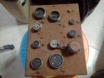
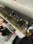
Now, we go into uncharted waters. The A27, ( special relay box).
Its the box in the rear bay with about a thousand C-Plugs hooked to it. Remove all the C-Plugs. Remove the 4, (If I remember right) hold down bolts. Take the A27 out. Remove the two screws that hold the cover and base together. The base get set off to the side. Look at the guts and see if there are any broken/ burnt wires. The look at the A5 card. million wires hooked to it. And broken parts? Burned parts? Signs of the card getting hot? Then remove the 4 nuts holding the A5 to the side of the box. Look at the back side of the card. Burns? Traces burnt through?

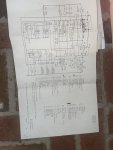


Yes you did post that earlier, I just now know that I was looking at the whole card and not just a segment. And just a question for clarification, do I need to disconnect everything from the card for the test?I posted the schematic of the A5 card a couple of posts back.
Here it is again..
View attachment 859524
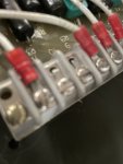
Here is the test setup and test procedure for A5
View attachment 859521
View attachment 859522
View attachment 859523
 Once was good enough for me.