• Steel Soldiers now has a few new forums, read more about it at: New Munitions Forums!

  • Microsoft MSN, Live, Hotmail, Outlook email users may not be receiving emails. We are working to resolve this issue. Please add support@steelsoldiers.com to your trusted contacts.


Bought another non-running 802a, begins to start, then falls off (Now a fix up thread)

Digger556

Well-known member
Steel Soldiers Supporter
232
534
93
Location
Denver CO
After starting reassembling and starting this unit up, I through a load on it. The unit was very shaky for a 802a, even after I tighten some loose isolator bolts. The unit could pull 6000 watts and seemed to be running fine, but anything over 3000 watts and the overload fault would trip after a minute or so. On the suggestion of a few members, I bought some Deoxit and hosed the S6 and S8 and exercised them thoroughly. I haven't retested it yet because the vibration issue really needs to be addressed. I fired up my other 802a for comparison and this one is much worse, so something is going on.

Since this unit had major oil pressure issues due to a stuck relief valve, I pulled the valve covers and inspected the push rods for bending per the TM. All looked good, so I reassembled the unit per the book procedure, waiting 90 minutes before hand turning the engine and restarting it. I also pulled the back cover of the genhead and look for a loose bearing. All looked good there. I also made sure the IPs were rotated to the same position, fully counterclockwise. It's worth mentioning that it seems to run good, pulls a full load, and the exhaust manifold is nice and dry with minimum soot buildup.

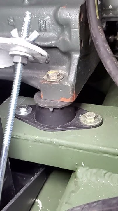
The front of the engine / genhead combo moves considerably more on its isolators then the rear. I've been thinking about what Guyfang has mentioned in several threads about the isolators, especially since the forward ones were missing hardware like someone had been messing with them. I'll look for part numbers tomorrow when the light is better, but here is some slow motion video of both. It doesn't look good.:ROFLMAO:


What do you all think?
 

Digger556

Well-known member
Steel Soldiers Supporter
232
534
93
Location
Denver CO
Way too much motion.
That's an understatement. It makes my other 802a look like an 803a.

I will try swapping isolatators from another 802 to start with and hope that is the issue, otherwise it is likely the genhead and engine need to be separated.
 
Last edited:

Guyfang

Moderator
Staff member
Moderator
15,904
22,183
113
Location
Burgkunstadt, Germany
There is one other possability. When you have the isolatators out, see if they have a part number on them. Check that against the -24P. If someone put MEP-803 isolatators in the set, that could be the problem. The 802A has a much stiffer isolatater.
 

Digger556

Well-known member
Steel Soldiers Supporter
232
534
93
Location
Denver CO
There is one other possability. When you have the isolatators out, see if they have a part number on them. Check that against the -24P. If someone put MEP-803 isolatators in the set, that could be the problem. The 802A has a much stiffer isolatater.

Well, no luck here.

The paint shaker shows 88-21070-1 isolators, which crossreference correctly with-24P part number (88-21070-3)


My 803a uses 88-21070-2 isolators. The -24P calls out 88-21070-4, which I can't cross-reference, but the convention follows similar to the 802 isolators.
 

Digger556

Well-known member
Steel Soldiers Supporter
232
534
93
Location
Denver CO
Looking at the wear pattern in the skid base and broken weld in the left battery area, this unit has been shaking hard for a long time.

20230802_205248.jpg
 

Digger556

Well-known member
Steel Soldiers Supporter
232
534
93
Location
Denver CO
At this point, it seems like I need to separate the engine and genhead to verify proper assembly and/rotate their relative positions.

For those that have done this, is it possible to separate the two in the enclosure just enough to unbolt the genhead from the flywheel and re-index them to each other? (Rotate the rotor 90° relative to the crankshaft? Or am I stuck disassembling the majority of the enclosure?
 
Last edited:

Digger556

Well-known member
Steel Soldiers Supporter
232
534
93
Location
Denver CO
At this point, it seems like I need to separate the engine and genhead to verify proper assembly and/rotate their relative positions.

For those that have done this, is it possible to separate the two in the enclosure just enough to unbolt the genhead from the flywheel and re-index them to each other? (Rotate the rotor 90° relative to the crankshaft? Or am I stuck disassembling the majority of the enclosure?

Went ahead and disassembled the genhead in place by removing the rear sheetmetal and sliding the housing and stator out the back after supporting the engine.
20230806_170106.jpg

The rotor looked visibly off center when observing the gaps between rotor poles and the stator laminations.

20230806_161103.jpg
20230806_161059.jpg

I placed a dial indicator on the rear bearing and measured .021" of total indicated runout (TIR)
 

Digger556

Well-known member
Steel Soldiers Supporter
232
534
93
Location
Denver CO
I pulled the rotor out and set it up on the lathe between centers to measure runout. Axial runout on the adapter plate was .006", measure mid-radius.
20230806_173951.jpg

Since the adapter is sheet metal and not necessarily true, I removed it and the support bearing and remeasured axial runout on the rotor's mounting flange and came up with .002" TIR. To help eliminate any contribution to the problem, I made a skim cut to square the pilot bore and mounting flange. You can see the runout on the partially machined face.
20230806_181242.jpg
20230806_181903.jpg
 

Digger556

Well-known member
Steel Soldiers Supporter
232
534
93
Location
Denver CO
With the rotor out, I measured axial runout on flywheel face and didn't see anything out of the ordinary.

Reassembling the rotor onto the flywheel, I remeasured runout at the end of the shaft and was still getting at least .020".

I called it a night, but tomorrow I plan to remove tbe rotor and measure radial and axial runout of the adapter when installed on the flywheel to determine what demon I'm fighting here.
 

Digger556

Well-known member
Steel Soldiers Supporter
232
534
93
Location
Denver CO
The mystery deepens...


I measured flywheel runout again from a more consistent point on the engine block. Found a low spot measuring .010". Pulled the flywheel and found out its about 1/8th inch too big to fit in the lathe. The crank bolts were not fully tight and the mating face of the crank has a few rough spots, so this could be a contributing factor.
20230808_221915.jpg

I setup my rotary table and measured baseline radial and axial runout. (0.000" axial, 0.0005" radial)
20230808_221928.jpg

Leveling the flywheel, I found a high spot about .004" in a different location from before. Radial runout was basically zero, so that's some good news.
20230808_223613.jpg


Tomorrow I'll clean up the crank face, measure runout there and then look at the adapter plate again.
 
Top
AdBlock Detected

We get it, advertisements are annoying!

Sure, ad-blocking software does a great job at blocking ads, but it also blocks useful features of our website like our supporting vendors. Their ads help keep Steel Soldiers going. Please consider disabling your ad blockers for the site. Thanks!

I've Disabled AdBlock
No Thanks