Well, a short term set back. The light bar is together (sans lens) and works, but makes a loud buzzing/hissing sound when supplied with 24V. On 12V, there is no noise. The bar is supposed to be able to handle 12-30V range. It seems as if one of the voltage regulators on one of the light module circuit boards is just not happy dropping the 24V down to the level it needs. I'll need to pull all the reflectors off, and see if I can determine which light module board is not happy. May need to disassemble completely, and test each module on 24V. If only one board has a flunky voltage regulator, then I will buy another (3rd) light bar, possibly shorter, and swap out the funky board, then reassemble.
Even though it is LED, it makes a lot of light and puts off a lot of heat, especially when only 6" away from it during working on it.


 69.9 KB Views: 49
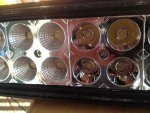 56.6 KB Views: 39
")
