• Steel Soldiers now has a few new forums, read more about it at: New Munitions Forums!

  • Microsoft MSN, Live, Hotmail, Outlook email users may not be receiving emails. We are working to resolve this issue. Please add support@steelsoldiers.com to your trusted contacts.


Glow Plug System Video

flyfishtrailer

Well-known member
Steel Soldiers Supporter
518
984
93
Location
Cool, CA
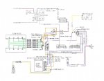
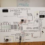
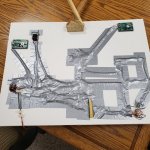
As a newbie to CUCVs (and auto mechanics in general), I have tried to use all available resources to help me problem solve issues. All of you here have been extremely helpful with insight and wisdom. During a random search today, I found the video (link below) that someone took a lot of time to create to show how the CUCV glo plug system works. This makes it very simple to understand what the GP card does. Thought I would share (many of you may have already seen it and I suppose one of you probably created it.

CUCV Glow Plug System Video - YouTube
 

Squibbly

Well-known member
406
1,030
93
Location
South Carolina
The video is in the CUCV Helpful Threads Sticky, under the Glow Plug System, GP Module Operation. It's been there for many years.

GP System Video

I still have the display board that we constructed for shows etc.

I'm glad to hear that you found the video helpful.
Wow. Really well done.
Got a picture of the wiring on the back of that foam board?
I'd love to see a video on the details of how it was constructed.
So many questions...starting with how did you get the voltage meter to come up to 13+ after start without a generator charging the batteries, or were you just manually turning a pot on a DC voltage supply to simulate it?

HPI0.gif
 
Last edited:

antennaclimber

Moderator
Moderator
Steel Soldiers Supporter
1,351
893
113
Location
State College, PA
I used a dual voltage variable power supply to simulate the DC voltage characteristics of the CUCV. One output simulated the 12V side and the other output simulated the 24V side.

We had to add voltage regulators to the volt meters to reflect the true voltage. Out of the box they would not indicate the voltage that the lab grade power supply was providing.. Just goes to prove what you can you expect from a low cost meter.
 

Attachments

Last edited:

WWRD99

Well-known member
Steel Soldiers Supporter
898
1,373
93
Location
York Pa
I used a dual voltage variable power supply to simulate the DC voltage characteristics of the CUCV. One output simulated the 12V side and the other output simulated the 24V side.

We had to add voltage regulators to the volt meters to reflect the true voltage. Out of the box they would not indicate the voltage that the lab grade power supply was providing.. Just goes to prove what you can you expect from a low cost meter.
I always wondered how the glow plug card knew when the engine started, now I know how! My truck needs new plugs as the system works but doesn't like to start when it's below 40 or so...one more thing to add to the list of parts! It really is a simple setup that works very well.
 

Squibbly

Well-known member
406
1,030
93
Location
South Carolina
I used a dual voltage variable power supply to simulate the DC voltage characteristics of the CUCV. One output simulated the 12V side and the other output simulated the 24V side.

We had to add voltage regulators to the volt meters to reflect the true voltage. Out of the box they would not indicate the voltage that the lab grade power supply was providing.. Just goes to prove what you can you expect from a low cost meter.
Nice.

TBH, I was hoping you were going to tell me there were cables running from the back of the board, out one of these doors, to a CUCV that you were remotely starting with this board, and making all this happen in real-time.

The temp pot gave me doubts. 😂🤣

1642517189886.png

I bet you probably could if you had a STE/ICE foam board. 😁
 

Squibbly

Well-known member
406
1,030
93
Location
South Carolina
No wires to truck, it's just simulating the CUCV GP system.

At a MV show it's a little difficult to stuff a full sized CUCV in a cardboard box and set it up on a table top!

I can't even member the last time I had this display set up and working. Had to be at least 6 years ago.
Did you hand draw that schematic, or print it out on a plotter?
If you printed it, do you still have the image?
The one in the manual is incorrect. :)
 

WWRD99

Well-known member
Steel Soldiers Supporter
898
1,373
93
Location
York Pa
We corrected the one that was in the TM. I had a friend of mine print the sign for us.
He had a graphic arts shop and was able to do that for me. I then went over it by hand to enhance the color of the lines.

Here is a color schematic for the GP system.
That's a great drawing of how it works! Hope it's ok to download for future reference.
 

Squibbly

Well-known member
406
1,030
93
Location
South Carolina
We corrected the one that was in the TM. I had a friend of mine print the sign for us.
He had a graphic arts shop and was able to do that for me. I then went over it by hand to enhance the color of the lines.

Here is a color schematic for the GP system.
Did you 'dado' a block of wood, and just stick wires into it at the correct spots for the PCB connections?

1642611503687.png
 
Top
AdBlock Detected

We get it, advertisements are annoying!

Sure, ad-blocking software does a great job at blocking ads, but it also blocks useful features of our website like our supporting vendors. Their ads help keep Steel Soldiers going. Please consider disabling your ad blockers for the site. Thanks!

I've Disabled AdBlock
No Thanks