In case anyone wants to install this rear steer system, I will give you my experience with the installation on my M998 with rear winch installed. My hope is to help some of you guys that do this avoid all the pitfalls I ran into that cost me time and lots of wasted $.
I will defer the use of this system for a another post as I need to try it out a bit more and form opinions.
I was fortunate and only ran into one rusted, stripped grade 8 bolt and it was a PITA to saw off! I am slow, and we still have the Florida Inferno here so I could only work on it a couple hours a day so it took me three weeks to get-r-done, mostly because I wasted a great deal of time and $ trying to make my own hydraulic hoses which ended up getting chucked to the dump.
Mounting Choices
There are two options for placement of the rear steer hydraulic cylinder. You can request a mounting plate for in-front or behind the diff.
After ordering the cylinder, you must call in and let him know if you want to mount the cylinder behind the rear diff, or in front of the rear diff. They will them make up the appropriate mounting plate for you. You do not get both!
If you elect to mount in front, you have to remove your fuel tank and make it safe, and then modify it using fire! Replacement fuel tanks are now expensive! And modifying can cause leaks resulting in tank replacement, and another new tank to modify again!
So I elected to mount in behind the rear diff. Be aware that if you stock military wheels, you may rub the tie end rod into the wheel. If you have aftermarket wheels, and the edge of the tire extends beyond the body line, you may have sufficient spare and not rub. If you rub, you have to either shorten the steering limit, or purchase wheel spacers to move the wheel out further. I already had civi wheels so I did not have any issues
First, I took two measurements. I placed a scratch on each of the tie rod mounts, and carefully measured the distance from wheel to wheel so I had a chance to maintain the rear alignment when done. I also placed a scratch on the diff and recorded the measurement from each tie end rod mount to the mark on the diff. If you leave the wheels on the ground, pretty much you are ok as they don’t move easily during the installation process.
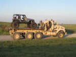
Rear Winch Mounting and Rear Winch Plate Compatibility
I have the m998 WINCH MOUNTING PLATE 12469385 REAR 5340-01-485-5962 and this system is compatible with the rear winch mount plate. However, it appears that the winch I have mounted is a bit large, and the electronics housing that is normally on the top of the winch. Fortunately, the winch I have is able to remote mount the controller that is on top so I could get clearance for the winch.
You need about 5 inches of space behind your winch for the hydraulic cylinder to fit.
Operating Modes
You can install a “Double Pilot Operated Line Lock”. If you do not install this, you have to hold the button, or joystick, of the pump to maintain the turn, and when the control is released, the cylinder will self-center by-itself.
If you elect to install a Double Pilot Operated Line Lock, the wheel will remain locked in position if you release the control of the pump, and you have to “bump” the control to get the wheel to return to center.
Extra Materials
Despite the postings on the thread, the only thing you get when you purchase the BulletProofRearSteer “system” is the hydraulic actuator. No electronics, no air actuator/disablers, no controls, no hoses, no pumps, no bolts – just the cylinder and mounting plate.
This is all you get:

Notice that on each end there are a pair of spring covers with two U bolts, locking the hydraulic rams. These covers should be retained and used for long highway drives, where you want the rear steer mechanically locked and incapable of any use.
First off, do not attempt to make your own hydraulic hoses! I wasted a ton of $ and they leaked the expensive hydraulic oil. Instead, go to a local hydraulic shop and have them make up
two hoses, usually while you wait, to the following spec:
- 128” in hose length in 3/8” ID USA made hose. This will be plenty long if you mount it und the rear pass seat.
- 3/8" JIC 37° Female 90° Elbow Hydraulic Hose Fittings For 3/8" I.D. Hose (6FJB6)
- 6SB6 straight swivel connecter for the cylinder end
- Two of these. Total was just over $300.
Believe me, you will save a TON of wasted $ if you have a professional make them up! I did not elect to use bulk head fittings as that would be four more possible leaks. The fewer number of connections, the less likely there are problems.
You need to spend about another $1K to get everything you need. Here is the list of components I bought for Rear Steer to function:
- The four bolts to mount the cylinder to the frame cross-member are ½” bolts with course thread. The bottom two are 3.25” and the top two are 3” long. Per the instructions, you need about ½” more and so I bought four ½” course 3.5” long grade 8 with new washers and Teflon lock nuts.
They told me I would need to Sawzall the top two bolts off as they hit the brake calipers as they come out the back (caliper) side. However, I was able to wiggle them both out without problems even though they did touch the calipers while I pulled them out.
The instructions state to then mount the new longer bolt reversed the original way since they are longer and will not go it with the caliper interference. I had to remove the cylinder from the mounting plate to get the lower ones started. So the bolt head side will be towards the cylinder, and the nut will be on the caliper side.
I also found it easier to remove the locks with the cylinder removed as it was glued together with paint.
You will also need to have four-six ½” washers for the top two bolts to act as spacers behind the mount bracket. I used two for each of the top two bolts.

I spent about $100 at the local Ace Hardware on Grade-8 nuts and bolts.
- RH TIE ROD END w/Nut & Pin ; Mil; 12338311-2 5577742 2530011892195 – Qty 2 – there both need to have right hand threads.
https://www.ebay.com/itm/184563188637
Total was just over $100
- 3 Quart Double Acting Hydraulic Pump Dump Trailer Unit 12V Control Kit SAE#6
https://www.ebay.com/itm/284912490265
Total was about $200
- Only needed if you desire to lock the wheel position:
- Double Pilot Operated Hydraulic Check Valve, #6 SAE Ports, 11 GPM Max Flow https://www.ebay.com/itm/276222669551
You will need two more hydraulic hoses to hook this up, and ypu will need different hoses than what I speced out above.
- 4 Guage sold cooper battery wire – 10 feet black and red, and (6) 4-gauge butt crimp connectors
About $25
- DC 12V - 24V Automatic Reset Circuit Breaker Circuit Breaker with Cover Stud Bolt for Automotive and More (50 Amp)
https://www.amazon.com/dp/B08L7PVJ88
About $10
- Car Circuit Breaker 30A AMP w/Manual Reset Switch
https://www.amazon.com/dp/B0BRV88HHC
About $20
- Optional: If you want a joystick rather than the "Up" "Down" buttons that come as the stock pump controller:
- Rear Steer System for Humvee
https://bulletproofrearsteer.org/
About $2K. Delivery took approx. 4 weeks.
- Mobil - 100817 DTE 26, Hydraulic Oil, ISO 68, 1 gal. The pump needs only 3 quarts, but you need about another quart that the cylinder will take up.
https://www.amazon.com/dp/B00PM9KTC8
About $25
- One quart of SAE 75W-90 oil to top off or actually change the oil in both hubs when you flip the tie rod assemblies.
About $15
Mounting Tips
If you have the rear military winch plate and a winch, you will need to remove it. Don’t waste your time trying to shoehorn that heavy thing in there with the plate and winch installed.
I also have the Air-Lift Bumper, I think that is what it is called, I had to remove the one bolt that is forward, on each of the two braces, and just loosen the four bolts that tie the brace to the pintle. For the driver’s side, use a bungee-cord to hold it and out of the way or you will not be able to line up the found mounting holes. For the passenger side, you MUST remove the brace so you can cut it shorter.
This is the passenger side air bumper brace, before shortening:

And after it is shortened:

I used a jack with a 4x4 block of wood to lift the hydraulic cylinder assembly into place.
Make sure you put some kind of washers behind the mounting plate on top two bolts or it will not sit correctly. The bottom two bolts have a riser on the crossmember and if you do not put some washers the mounting plate will not sit flat.
I discovered that seems impossible to seat the bolts once you have it place. I ran a ½” drill bit through the top two holes completely through the cross-frame too. Once I did that, the top two bolts went right in, and then the bottom two bolts also fell into alignment.

Then I removed the tie rod bars and swapped sides, and installed the new tie end to the end of the steering cylinder.
Before knocking in the tied end rods, I confirmed the distance between the marks on the tie end rod mounts and the measurement to the diff were the same as before.
I bought four new sets of bolts for the tie end rod retainers. They were really rusty. I knocked off a lot of junk with a wire brush and gave the tie end rods a fresh coat of paint too.
Below is a picture of the hydraulic cylinder almost installed.

You will lose some hub oil when you flip the tie end assemblies side-to-side. I left the tires on the ground and they did not move. I changed the hub oil when everything was completed and it was safe to take off the wheels and not risk losing the alignment.
And one more pic with the winch plate installed:
 Hydraulic Pump
I placed the hydraulic pump in the compartment below the passenger rear seat. I ran a ground and +12V Four-gauge wires from the battery to the rear compartment. I placed a 30-amp circuit breaker in the rear compartment to make a convenient spot to turn off power. But I used a bus fuse to protect the wire mounted near the battery.
I then ran the controller for the pump to the front dash. It was just long enough to make it to the front center of the dog house.
Remember, unless you have successfully made up hydraulic hoses before, go to a professional hydraulic shop and have them made up while you wait. It is cheaper and won’t leak and is less frustrating!
Electrical
I used 4 AWG battery wire to run +12V and ground from the battery compartment to the rear pass seat storage area where the pump lives. I used a 50 AMP Fuse right off the +12V terminal and then a circuit breaker in the compartment near the pump.
The hydraulic pump comes with a two button push switch. I changed that to a single axis joy stick, and mounted the joystick to a console I built under the radio tray.
There are four wires inside the stock pump switch:
- Grey – controls one side solenoid (left vs right)
- Blue – controls one side solenoid (left vs right)
- Black – path to turn on pump motor relay, apply +12V triggers the motor on.
- Red – constant +12V
Basically, +12V applied to the grey or blue wires engages the solenoid on the right or left side of the hydraulic pump. The joystick will prevent engagement of both solenoids at the same time which would be bad! But to get the motor to start, you have to short the red and black wires at the same time. I used two 12V relays to control the motor off the joystick as shown below.
The joystick has four contacts, a pair for each side:
- +12V (red) on the left side to the grey wire
- +12V (red) on the right side to the blue wire
- (2) standard 12V automotive relays wired as follows, tied into the joystick:

Optional Joystick Wiring:
 Safety
I installed a manual switch, with indicator light, that disables the system entirely, so my dog does not accidentally bump the joystick while I am driving and trigger accidental crab walking at 45 MPH.
I have seen on TV shows where a linear actuator is used along with a mechanical catch to physically lock the rear tie rods in place as an additional safety measure. But that is beyond my technical skill.
Other Tidbits…
One thing that perplexed me was after I filled up the pump with hydraulic oil was how to bleed the air out of the system. The pump motor would rapidly spin up but the piston on the cylinder would not move. Leaving the motor running tripped the circuit breaker, which probably saved the motor.
After a couple days break from the project, it seemed to start working on its own. I am assuming that the air rose out of the system back to the pump. Certainly, the pump is not at the highest point in the system though.