• Steel Soldiers now has a few new forums, read more about it at: New Munitions Forums!

  • Microsoft MSN, Live, Hotmail, Outlook email users may not be receiving emails. We are working to resolve this issue. Please add support@steelsoldiers.com to your trusted contacts.

M108 crane body

firefox

General
Steel Soldiers Supporter
1,845
51
48
Location
Berkeley CA
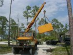
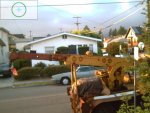
As some of you may know, I managed to bring an XM211 with an M108 crane body back from the dead. I just received my California Historic Vehicle plates.

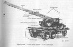
I now have to make the crane operational and I am very confused. Acording to the
manual the boom consists of two parts. One is stationary and the other moves within it
to extend and retract.

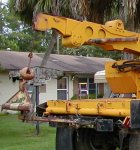
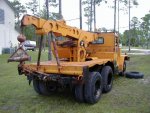
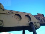
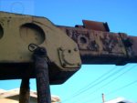
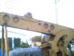
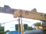
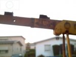
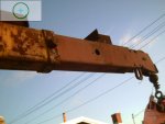
Mine, on the other hand, appears to have three parts. One stationary that looks original,
but the other two seem to be a hybrid. The two pieces slide within each other and are
positioned manualy, then secured with a large bolt. This assembly slides in the first part.

I am attaching two photos to show what I mean. They are not terribly clear, but I think you can see enough detail to follow what I am saying.

Just tell me if I am going crazy or not. My wife will handle the rest.

Bruce MVPA 23824
 

Attachments

Recovry4x4

LLM/Member 785
Super Moderator
Steel Soldiers Supporter
34,014
1,814
113
Location
GA Mountains
RE: body

I concur with Wayne, that is certainly something someone assembled for their needs.
 
48
1
8
Location
Fresno, Ca
RE: body

I would guess the middle one is powered and the inner one isn't. Looks like they tried to do the same as a M246.

The inner and middle boom from a M246 will fit on the M62 BTW. And might also fit on the M543.

John
 

firefox

General
Steel Soldiers Supporter
1,845
51
48
Location
Berkeley CA
Ok, so I'm not crazy after all...well, maybe a little.

The one thing that the previous owner said was that it had a 21 foot hook height.
He also said that it worked when he parked it, but I took that with a grain of salt.

What is the maximum hook height with a normal M108?

My guess is that they modified it for one of two reasons. Longer reach or heavier load.
Does either of these make sense?

Thanks a bunch guys!
Bruce
 

papercu

Active member
2,935
31
38
Location
Baxley, Ga.
Boom

Longer reach or heavier load
The longer the reach would mean a lighter load (without extra support)
Does any of the sections work with the hydraulic?
I think RAM said the hydraulic fitting on some models are really hard to find.
Wayne
 

cranetruck

Moderator
Super Moderator
Steel Soldiers Supporter
10,350
75
48
Location
Meadows of Dan, Virginia
The manual lists 16 ft as maximum reach.
For educational purposes, :wink: , here are the illustrations from the 1965 manual.
Whoever did the mod did a good job at making it look original. To manually extend something that heavy would surely require two people, I would geuss.
 

Attachments

TacticalTruck

Active member
927
48
28
Location
Va Piedmont
Are you sure it is a military boom? It apears to be similar in design to the M246/M819 boom which has an Austin-Western boom with a third unpowered section. You use the powered section to push and pull the unpowered section into position. You could probably put a bar between the brackets on top to use the powered section to push the middle section back. The crane would be operated with the middle section fully retracted or fully extended.
Jeff
 
48
1
8
Location
Fresno, Ca
Only the middle section is powered. If that is true with this truck, placing a bar between the middle section and the end section will not do anything except move the end section with the middle. On the M246 and M819, the pipe is placed under the boom and between the outer ridgid section and the end section when the inner boom (crowd) is extended all the way. Then you retract the middle section and the pipe will hold the end section out and the middle will slide back. Then you put the pins (I need these pins btw) through the middle and innner boom. And then remove the pipe and you can extend the middle boom (crowd) again and you are out there at 26'.

John
 

Recovry4x4

LLM/Member 785
Super Moderator
Steel Soldiers Supporter
34,014
1,814
113
Location
GA Mountains
It looks like there are 2 extra sections. The yellow boom appears to be a modified original and it looks like there are 2 primer sections of boom. I would hope that they didn't eliminate the crowd cylinder that is inside the boom. Some pics for reference.
 

Attachments

DDoyle

Well-known member
Supporting Vendor
1,825
80
48
Location
West Tennessee
Are you sure that this is a M108 body - or does it just LOOK like a M108 body? Better would be to get the Austin Western model number. This should be on a tag on the shipper near the pivot point on the operator's side of the crane.

I've done a bit of research into military wreckers, and there were several that were tested in limited numbers. The XM62E5 had fewer hydraulics than the normal M62 - perhaps this is a similar situation. Posting photos of the data tag, as well as the operator's station, would be very helpful.

Best wishes,
David Doyle
 

SierraHotel

Member
278
1
18
Location
Haymarket, Virginia
It sounds like a civilian boom truck a company I work for once had. The first section was powered and you could extend and retract it with hydraulics.
The third section however, was not powered. You pulled the pin (an overgrown tire iron) and powered the arm below the mounting point and it would slide out (with a rather dramatic CLANG!). You would then reinsert the pin and now have a longer boom to work with.
 

firefox

General
Steel Soldiers Supporter
1,845
51
48
Location
Berkeley CA
Thank you all for replying!!!

My take on this is that everything other than the decking, and the last two sections of the boom are original M108. The last two sections of the boom do not look all that well made
as in factory production.

The pieces added to the top for manually extending the end section are definetly home made. They did leave the pieces of pipe to extend it with.

The controls and data plates are definetly a match for what is in the manual.

There was a mechanisim to control what appears to be a throttle cable mounted on the plate that carrys the data plates.

I took some more pictures, but I am still learning how to use this camera. It was a gift so I am not complaining.

The number on the data plate is hard to read from the photo so here it is:

A - 784 -

I'll attach a few more pics.

Thanks again,
Bruce
 

Attachments

firefox

General
Steel Soldiers Supporter
1,845
51
48
Location
Berkeley CA
Only the middle section is powered. If that is true with this truck, placing a bar between the middle section and the end section will not do anything except move the end section with the middle. On the M246 and M819, the pipe is placed under the boom and between the outer ridgid section and the end section when the inner boom (crowd) is extended all the way. Then you retract the middle section and the pipe will hold the end section out and the middle will slide back. Then you put the pins (I need these pins btw) through the middle and innner boom. And then remove the pipe and you can extend the middle boom (crowd) again and you are out there at 26'.

Hi John,
I am thinking then that the brackets on the top are for retracting to the right spot
Putting the pipe in place and using the cable to pull the extended section back one
space so that the holes line up.
This would explain why there are two pieces of pipe, since there are three hole positions.


does this make sense?
Bruce
 

Dieselsmoke

New member
1,146
2
0
Location
CA/NV
firefox said:
Ok, so I'm not crazy after all...well, maybe a little.

Bruce
A little? Maybe a LOT Bruce :shock: :lol: :lol:

John, good to see ya here! If anyone knows wreckers John does...how many ya got now? Didn't get to talk much at Tower, you disappeared rather quickly.
 

firefox

General
Steel Soldiers Supporter
1,845
51
48
Location
Berkeley CA
I knew I couldn't hide it for ever......Hi Bill!

Now you see what I have been doing for the last year.

Bruce
 
48
1
8
Location
Fresno, Ca
Bill,

Yeah, You came late and I left Tower early. I had to get home Friday night to hit a Caterpillar swap meet on Saturday morning. I have three wreckers total now. Two M62's and now the M819(couple of weeks old). I just got done pulling the end section with the pully out of the middle section. Somebody in the military forgot to put the pins in that keeps the end section pinned to the middle section. Therefor the end section got sucked into the middle section. The tractor wreckers have the superior swing mechanism as apposed to the M62 that swings with two timed rams.

Firefox.

Middle section is powered placing the rods between the middle section and the end section will not move the end section out. The reason that there may be two rods is for stowage purposes. The tractor wreckers use a 3 piece rod(which i am lookinf for BTW). The rod is only used to lengthen the boom. To retract it, you merely pulley the hook gently up the the pulley on the end section and it will retract the end section in. Then you can pin it where you want. It is hard to explain, you really have to think about how it works. Kind of backwards from what you would expect.


John
 
Top