

- 25
- 107
- 28
- Location
- Oregon
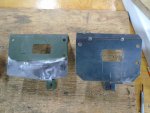
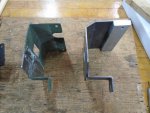
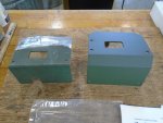
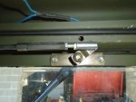
I bought a NOS electric windshield wiper kit and thought I would do a write-up of my installation. After I purchased the kit and read the instructions on how to install it I realized that I would have to take my hardtop off to install. I didn’t really want to have to take the hardtop off and cut the rubber weather stripping seal, so we redesigned some parts of the kit so that the top could remain on while installing the electric wipers. After thinking about the best way to proceed forward we modified the bracket that the wiper motor would mount to. It started looking like more modification to the bracket that holds the motor would need to be done and we ended up just making a whole new bracket with holes in a better location and added material. We machined a piece of aluminum that fits snugly into the inside lip of the hardtop and screws into the new bracket we made. This new bracket keeps the motor further away from the windshield frame and doesn’t require drilling holes into the top of the windshield frame. My truck already had two holes that were drilled into the middle section of the windshield frame, so we worked around that and made a plate with a stud on it to secure the new wiper motor bracket. We made an oversized stainless steel nut to tighten onto the stud. The wiper motor is very secure being attached this way
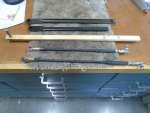
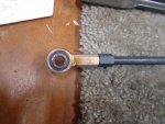
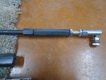
When unpacking the kit we noticed that the connecting rod links that attach to the motor had plastic bushings that were cracked and just in general didn’t look like they were in very good shape. We were having trouble of thinking of a way to make new plastic bushings that would fit into the hole, so we ended up making new connecting rod links to attach to the motor. We made two new arms out of 5/16”steel rod and threaded both ends on the lathe. On each of the new arms we made we screwed spherical rod ends on and a special locknut that we made that would also allow us to adjust the length. On the other threaded end of the connecting rod link we reused the ball joint linkage that came with the original arms and also made locknuts to allow for adjustment. We also made a nut that was only partially threaded and bored out to cover the exposed threads. Because we are using the spherical rod ends to attach to the motor we now needed to make a new arm. This part is made out of stainless steel. I painted the new motor bracket with Rapco paint; the arms/nuts that we made we parkerized them to prevent things from rusting.
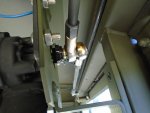
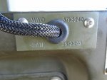
We weren’t too thrilled in having to drill a big 5/8” hole on top of the dash, especially with being so close to the edge. We decided on going through the front of the dash, which still wasn’t ideal since drilling any big hole into the truck bothers me, but we thought this would be the best route. There already were two little holes in the dash and we ended up drilling in between these two holes and then made our own MWO engraved plate that we thought made things look better. We machined a piece of aluminum with a channel running down the middle of it to protect the wires so they wouldn’t be dangling loosely down to where they ran through the dash. We had to drill four holes into the windshield frame and threaded them for this protective cover to screw down. Installing the circuit breaker that was included with the kit was simple; there were a bunch of pre-drilled threaded holes on the firewall under the hood and the circuit breaker screwed down to one of the many choices without any issues.
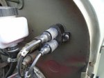
When it came time to put a plug in the air line that runs to the air wiper valve we realized it was a little difficult to remove the line from the air manifold under the dash, so we decided to just remove the line that tees off from the air wiper control valve and made a plug to put in there instead. The hard/soft air lines that lead to the air wiper motors were removed this way still and cleaned the clutter up.
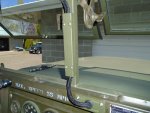
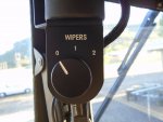
When it came time to connect the connecting rod links to the motor and where the wiper arm idler shafts stick through the inside of the cab we had to spend some time adjusting everything to get it just right. The idler shafts that protrude on the inside of the cab were positioned around the 2 o’clock position if you’re sitting in the truck. This way it was pretty close to the measurements that the instructions listed of 13.75” and 15.88” for the connecting rod links. We had quite a bit of room for adjusting the arms because of the way we made new connecting rod links that could be adjusted from either end if needed. After we got the connecting rod links adjusted close to where we thought they should be we then attached the actual wiper arms/blades and could position them how we thought looked correct because of the splined shafts. There were no issues after putting everything together when we tested it. We didn’t like having a plastic knob on the wiper motor so we made a new one out of steel and knurled it. Because of how the shaft for the motor was made it had a half-moon shape and we silver soldered a half-moon into the new knob we made. We then engraved the knob and an accompanying plate showing which position/speed the motor is at and after this we Cerakoted the new knob and plate. The wipers are parked towards the left (from point of view of sitting inside truck) and don’t obstruct the view at all. I am also able to open my windshield without any issues. Hopefully this write-up of my experience with the electric windshield wipers will be helpful to someone in the future. I know I did a lot of reading on here about them and struggled to find exactly what I needed to know/find a thread with pictures of everything I wanted to see. I took a lot of pictures and had a hard time deciding which ones are the best. Let me know if there are any questions or anything you’d like to see or know about my setup.
When unpacking the kit we noticed that the connecting rod links that attach to the motor had plastic bushings that were cracked and just in general didn’t look like they were in very good shape. We were having trouble of thinking of a way to make new plastic bushings that would fit into the hole, so we ended up making new connecting rod links to attach to the motor. We made two new arms out of 5/16”steel rod and threaded both ends on the lathe. On each of the new arms we made we screwed spherical rod ends on and a special locknut that we made that would also allow us to adjust the length. On the other threaded end of the connecting rod link we reused the ball joint linkage that came with the original arms and also made locknuts to allow for adjustment. We also made a nut that was only partially threaded and bored out to cover the exposed threads. Because we are using the spherical rod ends to attach to the motor we now needed to make a new arm. This part is made out of stainless steel. I painted the new motor bracket with Rapco paint; the arms/nuts that we made we parkerized them to prevent things from rusting.
We weren’t too thrilled in having to drill a big 5/8” hole on top of the dash, especially with being so close to the edge. We decided on going through the front of the dash, which still wasn’t ideal since drilling any big hole into the truck bothers me, but we thought this would be the best route. There already were two little holes in the dash and we ended up drilling in between these two holes and then made our own MWO engraved plate that we thought made things look better. We machined a piece of aluminum with a channel running down the middle of it to protect the wires so they wouldn’t be dangling loosely down to where they ran through the dash. We had to drill four holes into the windshield frame and threaded them for this protective cover to screw down. Installing the circuit breaker that was included with the kit was simple; there were a bunch of pre-drilled threaded holes on the firewall under the hood and the circuit breaker screwed down to one of the many choices without any issues.
When it came time to put a plug in the air line that runs to the air wiper valve we realized it was a little difficult to remove the line from the air manifold under the dash, so we decided to just remove the line that tees off from the air wiper control valve and made a plug to put in there instead. The hard/soft air lines that lead to the air wiper motors were removed this way still and cleaned the clutter up.
When it came time to connect the connecting rod links to the motor and where the wiper arm idler shafts stick through the inside of the cab we had to spend some time adjusting everything to get it just right. The idler shafts that protrude on the inside of the cab were positioned around the 2 o’clock position if you’re sitting in the truck. This way it was pretty close to the measurements that the instructions listed of 13.75” and 15.88” for the connecting rod links. We had quite a bit of room for adjusting the arms because of the way we made new connecting rod links that could be adjusted from either end if needed. After we got the connecting rod links adjusted close to where we thought they should be we then attached the actual wiper arms/blades and could position them how we thought looked correct because of the splined shafts. There were no issues after putting everything together when we tested it. We didn’t like having a plastic knob on the wiper motor so we made a new one out of steel and knurled it. Because of how the shaft for the motor was made it had a half-moon shape and we silver soldered a half-moon into the new knob we made. We then engraved the knob and an accompanying plate showing which position/speed the motor is at and after this we Cerakoted the new knob and plate. The wipers are parked towards the left (from point of view of sitting inside truck) and don’t obstruct the view at all. I am also able to open my windshield without any issues. Hopefully this write-up of my experience with the electric windshield wipers will be helpful to someone in the future. I know I did a lot of reading on here about them and struggled to find exactly what I needed to know/find a thread with pictures of everything I wanted to see. I took a lot of pictures and had a hard time deciding which ones are the best. Let me know if there are any questions or anything you’d like to see or know about my setup.
Attachments
-
 2.3 MB Views: 9
 -
 2.4 MB Views: 9
 -
 2.4 MB Views: 9
 -
 2.3 MB Views: 9
 -
 2.4 MB Views: 9
 -
 2.4 MB Views: 9
 -
 2.3 MB Views: 9
 -
 2.3 MB Views: 9
 -
 2.3 MB Views: 9
 -
 2.4 MB Views: 9
 -
 2.3 MB Views: 9
 -
 2.2 MB Views: 9
 -
 2.4 MB Views: 9
")