• Steel Soldiers now has a few new forums, read more about it at: New Munitions Forums!

  • Microsoft MSN, Live, Hotmail, Outlook email users may not be receiving emails. We are working to resolve this issue. Please add support@steelsoldiers.com to your trusted contacts.


M916 - understanding hyd system/wet line

zebedee

conceptualizer at large
Steel Soldiers Supporter
1,604
658
113
Location
Central NY
Further to these threads:

http://www.steelsoldiers.com/showthread.php?127106-M916A1-Little-Stuff
http://www.steelsoldiers.com/showthread.php?123032-M916A1-w-w

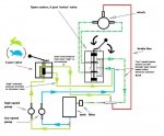
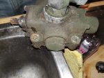
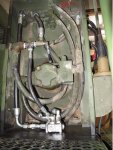
I wanted to fully understand the schematics of the PTO hyd/winch system with the plan to add the A3 wetline kit for trailer hydraulics.

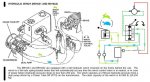
It appears that the direction valve is a spool type - 'motor' or open center and the speed valve adds high speed to the low speed rather than changing to high speed. This is done by simply doubling the volume - a both pumps are 20 Gpm (DS Edit - post #13)

I am not totally aufait with hydraulics - so I stand corrected. PLEASE CORRECT IF APPROPRIATE!

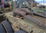
Plan is to add 't's to the low speed circuit, then running just two lines to the bulkhead below the winch - see A3 pic.

John's added front winch would have had to have an additional motor valve with four lines similar to the existing direction valve (P T A B - pump, tank and two reversible flow lines to the winch motor).

NB - 916 (std system), A1/A2 electric idle control, A3 added wetline.
 

Attachments

Last edited:

ReoRider

Member
165
11
18
Location
Vermont
Couple of questions...am I correct in assuming that you are planning to run a hydraulically operated disconnect trailer behind your M916A1? If so, where will you be setting up to operate the controls?

Basic existing set up on the truck is as follows--- When you turn on the dash PTO switch, the two large pumps are engaged on the Allison. The two control valves on the tower, each separately feed by its own pump, are of the open center type so that there is no pressure build up, when in the neutral position, and the fluid is just circulated around the loop. The main winch valve is a two position, motor valve type, set up with reversible flow to control in and out on the winch. The second valve, powered by the second pump, adds addition flow to the input of the main winch valve to increase the volume and hence speed of the winch in either direction.

To run another circuit from the pumps (your trailer), you will need to add another control. In the M916A3, and I believe in the M916A0, the second valve (additional volume one for the winch mentioned above) is a two position model. In the "up" position it sends pump flow to the auxiliary hydraulic connectors that you will want to install. However, there must be a cylinder connected or additional valves to control the trailer, or you will just build pressure to trigger the pressure relief valve. Hence the question about where do you want to be standing to operate the trailer.

If you just add T fittings to the existing winch circuit, and then lines running to your auxiliary connectors, nothing will happen. With the winch valve in neutral the oil will by-pass and not be interested in what you have connected to the auxiliary. So, additional digging into the tower is necessary. The plumbing is kind of tight at the top of the tower, so when I added a new control for the front winch installation on the M916A1 it was best to just tap into the existing system for feed and return, and not try to replace the existing valves.

Hope this helps
John
 

zebedee

conceptualizer at large
Steel Soldiers Supporter
1,604
658
113
Location
Central NY
Thanks John...


Trailer needs pressure to cylinder controls on trailer goose neck - operated from the ground, adj gooseneck detachment point.
The idea I am following is from "remotes" I have on a farm tractor, that are pressurised by selecting a valve that does not 'kick out' while waiting to use the lines hooked to the remotes...

OK - so more digging is indeed required - this is why I tried to draw the schematic... Enlarged for comment:


The number and connections of hoses and the flows seem to add up through all operations.

I think the speed control valve is just a diverter valve not a spool valve...... comment.

First observation - the Brake line has +ve pressure, to release the spring brake, all the while the system is running until pressure drop/failure so there must be pressure in the return line collector 'T' inorder to generate pressure in the brake line.....?????

So how is this restriction generated...... smaller lines down stream, restriction orifice??? SOMETHING HERE IS NOT EXPLAINED ON THE SCHEMATIC.

So 'T's used to pick up pressure/return flow would work if correct location found with a higher and lower pressure points found. Otherwise the trailer cyl's won't work. (There is a diverter valve on the trailer)

Where on the schematic did you pick up flow and return to supply your front winch spool valve???


What we need is a Hawaiian with a 1/2" spanner to go do an inspection - but I can't give details as that's against the rules. ; )
 

Attachments

DrillerSurplus

New member
443
7
0
Location
Salt Lake City. UT
I think the speed control valve is just a diverter valve not a spool valve...... comment.

First observation - the Brake line has +ve pressure, to release the spring brake, all the while the system is running until pressure drop/failure so there must be pressure in the return line collector 'T' inorder to generate pressure in the brake line.....????? I am 99% certain that the line you have labelled as "brake line" is actually a case drain.- see comments on your "hyd schematic A" .


So how is this restriction generated....see below.. smaller lines down stream, restriction orifice??? SOMETHING HERE IS NOT EXPLAINED ON THE SCHEMATIC.

So 'T's used to pick up pressure/return flow would work if correct location found with a higher and lower pressure points found. I agree with zebedee that T's will NOT work.

Where on the schematic did you pick up flow and return to supply your front winch spool valve???


How does it build pressure to release brake? TM says the winch's brake is spring loaded to hold if there is not at least 200 psi hydraulic pressure (in drilling winches it is usually more like 400 psi). When you move the control lever to actuate winch, the hyd fluid in line to winch motor builds up pressure trying to turn against the brake and once it reaches the release pressure, the brake is released-usually through internal porting that you cannot see on outside of winch-which allows the winch to turn in desired direction. Once you return control lever to neutral, the pressure drops and brake is automatically reapplied.

I think the simplest way to tap into the hyd system is to get a 6 port diverter valve similar to this- hydraulic diverter valve and use hoses I labelled A & B on your "hyd schematic A" as the input. Then one pair of hoses on output side of diverter is connected back to winch valve where the hoses came off and the other pair of output hoses go back to your trailer. If you didn't want the high speed option you could tie in at A'.

If the trailer valves provide the directional control you need, you could also use a 3 port diverter valve to tie in at A or A' and run a return line from trailer valve to return manifold I labelled M on your "hyd schematic A".

You might be tempted to tie into system for pressure where I labelled X. Unless the valve for the winch is designed for "pressure beyond" and has the appropriate power beyond plug installed, it will very quickly blow the seals out in the valve (if not the the first time you build up significant pressure.) I am not near one of the M916A1's to check, but I am almost positive the valve is not designed for power beyond. On all this you need to make sure the valve & hoses you use are appropriate for the flow and pressure of your system.

Hyd schematic A-comments.jpgView attachment Hyd for winch on M916_TM 9-2320-363-20-2 page 4-759.pdf
 

ReoRider

Member
165
11
18
Location
Vermont
All good advice, DS is correct that the winch brake mechanism is internal to the winch, with just a small return (drain) line running from the winch housing. The late model A3 trucks have a boost valve with a second position to send pressure to the auxiliary fittings. You indicted that the controls for the trailer will be on the goose neck, so you can go with the simpler of the options that DS mentions for your trailer feed valve.

The problem, however, in working in the hydraulic tower on a vintage M916A1 is the tight quarters and the very stiff lines. How and where you connect your IMG_2067.jpgnew valve will be driven by access and these tight quarters. IMG_2173.jpgIMG_2100.jpgIMG_2090.jpgIn installing the front winch, I tapped into the output of the boost pump, before it went to the boost valve. This allowed the easy locating of the new valve and then ran a new line to feed the existing boost valve. As DS noted, the new valve was set up for power beyond, as the original boost valve followed it in series. I used the boost pump to feed the front winch to keep it separate from the system running the rear winch. This way I could conduct interesting frame stretching experiments(kidding), but felt more prepared for whatever might occur in the field.
 

DrillerSurplus

New member
443
7
0
Location
Salt Lake City. UT
ReoRider, that sure is a clean looking install on the front winch! How much pull is it rated for?

I agree that tapping in at the pump gives you a lot more room for ease of working & flexibility on where to install the new valve.

I have winch/5th wheel parts available now that we've converted another M916A1 for water truck/fire fighting service.

M916A1 water truck fs.jpg

This truck still has the hydraulics to run water pumps, I think it would be even better with a front winch- did you do a build thread on your install?
 

ReoRider

Member
165
11
18
Location
Vermont
DS -- The front winch is a hydraulic 20K from a 5 ton. Check out the link in the first post on this thread (M916A1-w-w). With your hydraulics still on board it would be a natural for your large white truck.

Just a chance question- do you still have the rear winch direction plate that is mounted on the top of the hydraulic tower. Mine has faded to dust and am in need of a replacement?
 

DrillerSurplus

New member
443
7
0
Location
Salt Lake City. UT
ReoRider- Wow- I read the thread on your install & I'm even more impressed.

As I thought about these posts, it seems like zebedee could also accomplish what he wants to do with a second 3 port selector valve installed right after the existing 3 port valve where existing line that currently returns flow to tank when not needed is the input to new valve. One new working port goes to the original return to tank circuit and the other feeds the trailer valve. The return line from trailer valve goes to the existing return to tank manifold. Sort of similar to what you did, but since it is on a working port of the existing 3 port valve, it doesn't need to be power beyond.

Hyd schematic A-comments#2.jpg
 

73m819

Rock = older than dirt , GA. MAFIA , Dirty
Steel Soldiers Supporter
In Memorial
12,196
314
0
Location
gainesville, ga.
Are the HETs hyd. system the same as the 916s ???, I will be needing to tap into the HETs system to run other hyds, (a knuckle boom, winch, and a lift cylinder), for a future project.
 

zebedee

conceptualizer at large
Steel Soldiers Supporter
1,604
658
113
Location
Central NY
... with a second 3 port selector valve installed right after the existing 3 port valve where existing line that currently returns flow to tank when not needed is the input to new valve. One new working port goes to the original return to tank circuit and the other feeds the trailer valve. The return line from trailer valve goes to the existing return to tank manifold. Sort of similar to what you did, but since it is on a working port of the existing 3 port valve, it doesn't need to be power beyond.
Thanks DS... however wouldn't 'piggybacking' a second diverter valve where you suggest pick up the highspeed pump output not the lowspeed one if so - would this be a problem?

I was hoping to avoid another valve, just going with 'T's' but even on the farm tractor, I have to throw a lever before the remote connectors get power.

The brake line assumption came from a high speed winch I have lying around that needs another pressurised feed before the brake will release, not internal with drain.

I will pull the cover tomorrow and take some pics of the stock system.
 

DrillerSurplus

New member
443
7
0
Location
Salt Lake City. UT
Are the HETs hyd. system the same as the 916s ???, I will be needing to tap into the HETs system to run other hyds, (a knuckle boom, winch, and a lift cylinder), for a future project.
They are quite a bit different, but same principles would apply. They have a stacked gear pump with 3 sections, you would choose one (or maybe more) of the circuits and plumb your new control valve in. Since you have multiple functions, I think it would make the most sense if you went the route ReoRider used and put your new valve equipped for power beyond in as the first in the circuit. You would need to get appropriate sections for your new valve since the knuckle boom and lift cylinder would probably have cylinder spools and the winch would have a motor spool. If you wanted to have different pressure limits on some of the functions you can get valve sections with adjustable pressure reliefs on each of the functions.

Photos below show what the valve used on the WAJAX knuckle boom lookS like

HYD valve for WAJAX knuckle boom  power beyond.JPGHYD valve for WAJAX knuckle boom  1.jpg

TM-9-2320-360-24P M1070 page 2-738 hyd system.jpg
 

DrillerSurplus

New member
443
7
0
Location
Salt Lake City. UT
Thanks DS... however wouldn't 'piggybacking' a second diverter valve where you suggest pick up the highspeed pump output not the lowspeed one if so - would this be a problem?

I think the pumps are the same @ 20 GPM, the high speed designation comes from adding the flow of the second pump to the first, so I do not think it would be a problem..

The brake line assumption came from a high speed winch I have lying around that needs another pressurised feed before the brake will release, not internal with drain.

I am most familiar with the Pullmaster planetary winches. Most of them do have a small fitting- usually 1/8 or 1/4 inch for an optional external brake release in addition to the internal porting that gets the pressure from the two main hoses that run the winch motor. Pressurizing that external brake release allows the winch to free spool and pay out cable when the winch line is pulled without needing to actuate the winch control lever for up or down.
 

zebedee

conceptualizer at large
Steel Soldiers Supporter
1,604
658
113
Location
Central NY
Thanks DS. Certainly a load more (read Total) experience your end of the stick!

I found the TM pic of the A3 setup, though I don't have the parts section to see if the valve on the A3 is the same as the A1/A2 with a plug removed or if is is a larger valve with more ports. Anyhow, the physical position of that valve in the A1/A2 is right up against the tower, so accessing it is not possible without moving it.

Would 'T'ing into that valve's supply and return work or is a second diverter valve reqd in series (which is not used in the A/3's to get the supply/return to the trailer)?

Assuming that the "Pioneer"(or other type) females on the bulkhead (trailer connections) hold pressure when not coupled.
 

Attachments

Last edited:

DrillerSurplus

New member
443
7
0
Location
Salt Lake City. UT
Thanks DS. Certainly a load more (read Total) experience your end of the stick!

I found the TM pic of the A3 setup, though I don't have the parts section to see if the valve on the A3 is the same as the A1/A2 with a plug removed or if is is a larger valve with more ports. Anyhow, the physical position of that valve in the A1/A2 is right up against the tower, so accessing it is not possible without moving it.

Would 'T'ing into that valve's supply and return work or is a second diverter valve reqd in series (which is not used in the A/3's to get the supply/return to the trailer)?
No, same problem, the fluid would just take easy route back to tank= no pressure.

Assuming that the "Pioneer"(or other type) females on the bulkhead (trailer connections) hold pressure when not coupled.
Correct, hydraulic QD (Quick Disconnect) hold pressure. Also as ReoRider pointed out, it would be a good idea to have 1 male & 1 female on bulkhead to make sure hoses are connected properly rather than 2 females on bulkhead and 2 males on the trailer hoses.

The valves look different. The A3 valve appears to have 4 hoses attached, but your schematic A and the TM page I posted show only 3 hoses. On the A3 hydraulic schematic, it looks like instead of the valve dumping oil back to tank if it wasn't used to add "high speed" to the winch, they instead used it to feed the trailer hydraulics. You might be able do the same thing. Only problen is that if there weren't any hoses hooked up to the trailer quick connects and you moved the control lever to send hydraulic fluid to them the fluid would have nowhere to go. That would be OK as long as a pressure relief is in the circuit. You couldn't leave it going over relief for a long time which would build a lot of heat-more than system could dissipate. On the drilling equipment, we often made a short jumper hose to bridge the QDs to avoid that problem- it also kept the QDs clean.
 

ReoRider

Member
165
11
18
Location
Vermont
Yup, the A3 valve is quite different- if there was lots of room, and pliable hoses, you could replace the A1 style with one. Not the case, so a good next step would be to decide where you want your new control valve to mount- would recommend inside the "tower" with handle coming through the side. As DS notes the best connection, both from a system perspective, and for the existing physical layout, would be to then feed it from the return line of the "boost " valve. The other connections to the new valve and the return manifold are then "new", so the hoses can be comfortably cut and placed in the space available. You will then have two lines going out to your quick disconnects.

Looking ahead, what is going to get loaded on the detachable--the wrecker? Or perhaps you would become unstoppable in then being able to drag home any number of dead cats?
 

zebedee

conceptualizer at large
Steel Soldiers Supporter
1,604
658
113
Location
Central NY
Yup, the A3 valve is quite different- if there was lots of room, and pliable hoses, you could replace the A1 style with one. Not the case,


Yeah - I have wondered if replacing the A1 valve with a 5 port double diverter valve would be viable but the
real-estate being premium may not allow elbows on the left side (facing forward) of the valve... as an aside, I am awaiting a logsplitter valve (scratch built for neighbour - 3 point tractor mount) and had thought about using one of them - spring to supply highspeed side of winch or detent to supply trailer remotes.... If I have to buy a new valve anyway - why not replace instead of add...

so a good next step would be to decide where you want your new control valve to mount- would recommend inside the "tower" with handle coming through the side.
... I had thought about a semi discrete handle through the floor of the tower, so that the end product resembles the A3 - as if it was an inservice upgrade - it would also remove the need to get up on the catwalk to select "trailer", just reach under as you walk to the gooseneck. [Pre post edit.. argument against this at end of post- left in for 'thought process']

Looking ahead, what is going to get loaded on the detachable--the wrecker? Or perhaps you would become unstoppable in then being able to drag home any number of dead cats?
Well... that is sort of the general idea, along with round bales, broken farm equipment etc., - however an 870 would be the eventual goal. Not sure that more dead cats (for me) would fly well with 'er-indoors. Also I would be able to do a little local work to maybe pay for some of this fun.


Correct, hydraulic QD (Quick Disconnect) hold pressure. Also as ReoRider pointed out, it would be a good idea to have 1 male & 1 female on bulkhead to make sure hoses are connected properly rather than 2 females on bulkhead and 2 males on the trailer hoses.
Yes - both of you are correct though looking at the A3 pic in post #1, I think I'll go with two different sizes of no-drip fittings - as linked in one of the other threads noted post one... Large return and smaller delivery. (for me, this would mean changing the fittings on the jump lines on the trailer and maybe carrying adapters if I were to 'lend' out the trailer). Another aside - the trailer once had a donkey engine on it (for non wet line tractors) originally so I may "restore" this function down the road for sale purposes - if I find an 870. Modification of gooseneck would also have to be reversible otherwise only a 6x6 tractor could pull it (~63" high fifth wheel!)


The valves look different. The A3 valve appears to have 4 hoses attached, but your schematic A and the TM page I posted show only 3 hoses. On the A3 hydraulic schematic, it looks like instead of the valve dumping oil back to tank if it wasn't used to add "high speed" to the winch, they instead used it to feed the trailer hydraulics. You might be able do the same thing. Only problen is that if there weren't any hoses hooked up to the trailer quick connects and you moved the control lever to send hydraulic fluid to them the fluid would have nowhere to go. That would be OK as long as a pressure relief is in the circuit. You couldn't leave it going over relief for a long time which would build a lot of heat-more than system could dissipate. On the drilling equipment, we often made a short jumper hose to bridge the QDs to avoid that problem- it also kept the QDs clean.
I like the short jump line idea - but I think that the "skid steer" type no leak/flush fittings will stay clean enough, quick wipe with the obligatory oily rag, also I think that I'll need to train myself to select "trailer" AFTER the lines are connected rather than risk a pressure relief by forgetting. So going back to Johns point of valve location (top of this post), I'll have to do the catwalk thing to hook hoses anyway.... I don't think it's a good idea to leave the hoses connected whilst driving - jack-knifing the trailer to maneuver tight spots may be an issue with hose wear/catching on the deck.
 

zebedee

conceptualizer at large
Steel Soldiers Supporter
1,604
658
113
Location
Central NY
Minor update - A local highway dept has just acquired an A3 from Germany (??) and will be pulling the winch/fifth wheel to make a plough truck. Anyway - I got a good look at the winch tower/remote lines and found that the High/Low speed valve as on the A1/A2's has a third 'Aux' position which supplies the remote lines for the newer M870A2 RGN. Probably has a detent in the Aux postn (with no detent on the 'High' seed position and sprung to home at the 'Slow' speed position.).

Fingers crossed I can make a deal on the take off parts!
 
Top
AdBlock Detected

We get it, advertisements are annoying!

Sure, ad-blocking software does a great job at blocking ads, but it also blocks useful features of our website like our supporting vendors. Their ads help keep Steel Soldiers going. Please consider disabling your ad blockers for the site. Thanks!

I've Disabled AdBlock
No Thanks