electricdiesel
New member
- 6
- 0
- 1
- Location
- Southern California
Hi,
New member here. What a wonderful site. I just got my hands on a MEP-006A Fremont 1974 last month with the Allis Chalmers turbo diesel engine. It has a little under 6000 hours. I've read the half dozen MEP 006A threads from other members on here and I'm having similar problems. Grateful for those posts and answers/help so far. I also watched some Matt Verley videos which gave me some more insight on potential user issues on the MEPs. I have also printed and read both TM 12 and 34 which were helpful, but I'm still stuck.
I got the genset and installed (2) 845cca marine batteries, poured the recommended quarts of coolant in it, put some #2 diesel fuel in her and it started! However, I tried plugging an impact driver in the 120V convenience receptacle to test for power and it doesn't turn on.
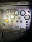
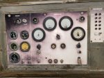
I held the s2/start switch for 15 seconds to get help the magnetic field started (source: Matt Verley), but the Volt meter just stays at 240V until I let go of the start switch and let it go back to run mode and then thr Voltmeters goes down to about 50V. The Hertz cycle meter stay at 48 or 0. I can't differentiate between what the true reading is. There is oil pressure and the battery ammeter is in the green. See attached picture.
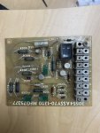
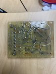
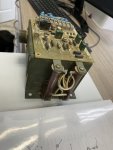
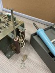
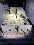
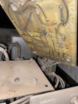
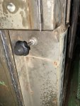
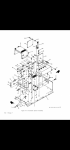
I checked the exciter assembly box (lots of dirt in it) and checked the back of the Voltage Regulator card and there's no burnt leads/soldering lines on the card. See attached pictures.
I saw an exciter assembly box online (since it sounds lioe the Voltage Regulator and card often quit), but I wanted to see what other remedys I could perform on it to get the 3 phase power it was designed to produce.
Any help and guidance would be greatly appreciated.
New member here. What a wonderful site. I just got my hands on a MEP-006A Fremont 1974 last month with the Allis Chalmers turbo diesel engine. It has a little under 6000 hours. I've read the half dozen MEP 006A threads from other members on here and I'm having similar problems. Grateful for those posts and answers/help so far. I also watched some Matt Verley videos which gave me some more insight on potential user issues on the MEPs. I have also printed and read both TM 12 and 34 which were helpful, but I'm still stuck.
I got the genset and installed (2) 845cca marine batteries, poured the recommended quarts of coolant in it, put some #2 diesel fuel in her and it started! However, I tried plugging an impact driver in the 120V convenience receptacle to test for power and it doesn't turn on.
I held the s2/start switch for 15 seconds to get help the magnetic field started (source: Matt Verley), but the Volt meter just stays at 240V until I let go of the start switch and let it go back to run mode and then thr Voltmeters goes down to about 50V. The Hertz cycle meter stay at 48 or 0. I can't differentiate between what the true reading is. There is oil pressure and the battery ammeter is in the green. See attached picture.
I checked the exciter assembly box (lots of dirt in it) and checked the back of the Voltage Regulator card and there's no burnt leads/soldering lines on the card. See attached pictures.
I saw an exciter assembly box online (since it sounds lioe the Voltage Regulator and card often quit), but I wanted to see what other remedys I could perform on it to get the 3 phase power it was designed to produce.
Any help and guidance would be greatly appreciated.
Attachments
-
 79.6 KB Views: 18
 -
 67.1 KB Views: 20
 -
 73 KB Views: 19
 -
 146.9 KB Views: 16
 -
 78.5 KB Views: 17
 -
 101.6 KB Views: 14