- 92
- 209
- 33
- Location
- Hampton, NH
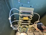
Resistor is installed. I was very happy that the resistor fits in the space that the original one resided in. I removed the old R12 and unsoldered the wires. I checked it with my meter and it was open circuit. I looked it over carefully and did not see any external evidence of overheating. I knew then this repair would fix the issue. I unbolted the resistor panel and angled it so I could get my drill lined up. I did not have to touch the wiring. I drilled 2 new holes for the new resistor and used the screws that secured the factory one. Other than partially covering the markings for R13, it fits like it was designed to be there. I soldered the wires and reassembled the panel. I used a shop vac with a very narrow crevice tool to vacuum up all the metal shavings from my drilling. I spent extra time making sure there were now shavings anywhere, especially around the terminals of the other components.
Finally the time came for the big test. I started at 3000 watts. Ran that for 10 minutes. Increased to 4000 watts for another 10 minutes then went to 5000. It had tripped out on overload after 3 or 4 minutes before. After 10 minutes went by, I was pretty confident I had fixed the issue. I ran it for 1 hour at a 5000 watt load. It was a very happy generator and so was i!
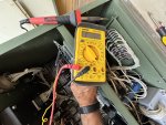
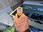
I then used my infrared temp gun and read the temps of the resistors. R10 was 112 degrees. R11 was 109 degrees and the new R12 was 98. I know resistors, by nature, create heat. That is why they were mounted using stand-offs. I am very confident that this new one will dissipate the heat better than the old designs. Finally I checked the voltage from terminals 4 and 1, 4 and 2 and 4 and 3 and they were all 5.6 volts. Just like they are supposed to at a 5K load.
I want to thank KloppK for pointing me to the burden resistors. Especially the method for testing them. I have a feeling that this information will be very useful for those of us with the aging 802's and 803'S. You guys are all amazing.
Just so you have it, here is the resistor info.
71-RE70G7R50
RE70G7R50C02
Vishay Wirewound Resistors - Chassis Mount
Mouser Electronics, Inc.
Phone: 800-346-6873
orders@mouser.com


Attachments
-
7.3 MB Views: 4

