• Steel Soldiers now has a few new forums, read more about it at: New Munitions Forums!

  • Microsoft MSN, Live, Hotmail, Outlook email users may not be receiving emails. We are working to resolve this issue. Please add support@steelsoldiers.com to your trusted contacts.


MEP Frequency Meter is Funny

steelypip

Active member
769
68
28
Location
Charlottesville, VA
My freq meter worked when I got the generator but didn't move during last month's scheduled test. Out came the kill-a-watt (which I had long before getting the generator because they're so blasted useful). I was careful to crank the speed control to the upper limit while I went inside for the kill-a-watt. I assumed that the knob hadn't been moved since last run, but I had no way to know for sure.

When I checked, I was making 64 Hz. Dialed it back down to 61 and loaded it down. I haven't investigated the meter and transducer circuit yet...
 

ETN550

New member
457
9
0
Location
Knoxville, TN
Maybe "We" can fix it??

Okay, I have been trying to figure out what to do.

I pulled the freq transducer out of my other 016B and put it on the bench and hooked up the original meter from the unit that was acting funny. The meter worked fine and exhibited no drift. Conclusion, bad transducer, as you all correctly predicted.

Found a new unit on line from Welscher instruments. 1% accuracy, 0 - 1mA output, 10K ohms. So that would work with the 1K resistor across the gage terminals. Only 1 problem, or maybe 2. The case is much larger. Biggest problem is $525.00 - OUCH :shock: Also waiting on a reply from Delks.

Swaped the good transducer into my gen and ran it tonight - Perfect, no issues. While it was running I disassembled the defective one started looking at it.

This is a very simple device of what appears to be all resistors and capacitors, or maybe some of those are diodes?? (It does output DC with AC input.)

One of the large rectangular ceramic 5K resistors looked like it was putting heat to the board under it. Maybe that is all that is wrong?? See pics. Not super bad but discolored.

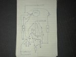
I made a wiring diagram (taken from the back side solder tracks) and have some pics.

I also thought about the possibility of installing a gas engine tachometer in the existing location and pulling a signal off of the 120vac somehow. Maybe a cheap solution to retain an analog gage and not modify the opening.

I would like to take a shot at fixing this simple board by replacing the defective component.

Any ideas where to start??? I was thinking of the resistor. What other components would cause the drift?? Capacitors?

Looking forward to some commments from the experts!! :-D

DSCN3008.jpg

DSCN3009.jpg

DSCN3010.jpg

DSCN3011.jpg
 

Attachments

Last edited:

derf

Member
926
13
18
Location
LA
The cap in the middle of pic 3 looks bad. When they distort and/or vent they are bad.
Caps don't last as long as most other electronic components, in general.
I'll bet if you replace that cap it will work fine.

What gen is this for? I may have an extra if it is the same as a 016 unit. I have one or two extra control boxes around here. If I do and it fits, you can have it for a reasonable amount. For $525 it should come with the rest of the generator, IMHO.
 

derf

Member
926
13
18
Location
LA
Found one "Technology Research Corp" "Frequency Transducer 60 HZ" "13211E6901" "Part no. 10380" "Serial No. 012482" LMK if you need it. There should be at least one more around here somewhere.
 

n1oty

Member
Steel Soldiers Supporter
170
1
16
Location
Taunton, MA
I agree with Derf that, at a minimum, that cap is bad. When I re-cap a section in my radios, I do all of them. I'd change the caps and re-test.

John
 

ETN550

New member
457
9
0
Location
Knoxville, TN
Derf, n1oty,

Thanks for coming through! The gen is the 016B, same as the 701A. The unit I found for $525 is probably made for some sort of large industrial control system hence the price. The container is much bigger so it probably is more complex inside.

Do you think the big rectangular resistor that has been heating the board is OK? Maybe change it as well?

I was thinking the caps would be responsible for a drift and I hear what you say as they are automatically assumed to be suspect components. The caps do not look all that bad. There is a coat of clear lacquer on everything and what looks like a distorted case on the cap is actually a drop of clear coat. Never the less, the caps are suspect.

Derf, Thanks for the offer on the replacement unit. I'll try the cap swap and see what I have. It is very easy to bench test this device with household 120 so I'll give it a try first, nothing to loose. The replacement caps and resistor should cost little. The resolder job should not be too hard as there is good space to work.

I did find a whole 016b control box advertised for sale that has the transducer in it. But the box is missing the generator voltage regulator assembly and the control board with the all the relays. So what is left is not worth too much. Not sure it is worth their price and shipping. I might offer them less and see.

Maybe I should look for a whole gen as parts for cheap. I have two very nice units and cannot be forced to use one for parts. A whole gen for $300 or so would be great for parts.

I'll report back after trying a cap and resistor change out.

Doug
 

Keith_J

Well-known member
3,657
1,313
113
Location
Schertz TX
The capacitor is failed and is probably failed with some DC resistance, causing the wire-wound resistor to see greater current which is heating the resistor. It should be fine but a quick test would be a good thing. You might have to remove it from the circuit, just one leg is fine. It is a 5 Watt, 5000 ohm. With the thermal damage, it must have seen at least 3 Watts. Since power is current squared multiplied by resistance, solving for current shows 25 milliamperes giving a voltage of 122 volts which is certainly possible.
 

ETN550

New member
457
9
0
Location
Knoxville, TN
Back Up and Running!!

I replaced the two capacitors this afternoon and now it works perfect, no drift. I used the household 120vac suicide cord and jumpered to the meter to make the adjustment. Then, running I tweaked it slightly according to the kill a watt. The capacitor that was identified in your posts was indeed blown on the bottom between the wires. The other capacitor looked okay but got replaced anyway as recommended.

Radio Shack did not have the big ceramic resistor so I did not mess with it.

Then I re-installed the good transducer that I had pulled from the other gen and calibrated it at 60Hz by adjusting its meter bias slightly.

Thanks to everyone's know how I saved a lot of time and money! And it is all original.

P.S Really like that Kill-A-Watt. Wish it would take more load but what a great little device!

Doug
 

derf

Member
926
13
18
Location
LA
I would not worry about the resistor. You're probably good to go for another 30 years on that part.
 

Keith_J

Well-known member
3,657
1,313
113
Location
Schertz TX
That resistor is called a wirewound or power resistor. 5 Watt size. I've seen them charred and still work, that is why they are made that way.

One reason I like military electronics. Designed to be repaired.
 
Top
AdBlock Detected

We get it, advertisements are annoying!

Sure, ad-blocking software does a great job at blocking ads, but it also blocks useful features of our website like our supporting vendors. Their ads help keep Steel Soldiers going. Please consider disabling your ad blockers for the site. Thanks!

I've Disabled AdBlock
No Thanks