

Scoobyshep
Well-known member
- 1,394
- 2,198
- 113
- Location
- Florida
Backstory: Years ago I obtained a mep004 for a good price, and it being the first in what turned out to be a fun hobby, I set it up to run as my backup power source. First thing that had to be done was the lower radiator connection. I found it was clogged and causing the set to overheat. when I took it apart to clean I had noted some serious corrosion damage to the housing, More on that later. Once I got it running (starter needed cleaned) I did a single phase conversion. I used the concept sewerzuk posted about, but instead of making bussbar cuts i changed the locations of the head leads on the reconnection board, Physically different but electrically the same. Once that was complete the set got moved into position.
Once there came the wiring and controls. Since I do motor controls professionally I had an abundance of parts at my disposal. After several evenings and weeks of work I had this setup to automatically start govern frequency and transfer power. This ran great for several years until I had a cannon plug failure. At this point the damage was bad enough for me to do a full recontrol of the set.
While starting the software writing process and arguing with myself which controller I wanted to use I came across another similar thread on this forum. That being said a huge thankyou to @peapvp for his work on the mebay conversion and willingness to help. While doing all this work it was also time for batteries (one they were getting weak, two the radiator was leaking on them) On my todo list was now repairing the corroded radiator connection, trying to find a replacement proved rather impossible.
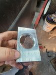
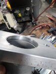
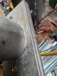
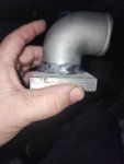
I started with a piece of aluminum plate long enough to cover the port. Then it was cut approx half way through with a holesaw sized to the OD of the fitting. Then it was bored through with a smaller blade (equal to the fitting diameter) this made a rather impressive press fit. This then provided me an excuse to buy a new tigwelder, and welded the fitting to the plate. Now for the shudders infront of the radiator, I made a set of brackets and used a DC linear actuator to pull them open when the coolant got hot enough
After several weekends of very hot work I finally got the set to a place I could start testing. more to come soon
Once there came the wiring and controls. Since I do motor controls professionally I had an abundance of parts at my disposal. After several evenings and weeks of work I had this setup to automatically start govern frequency and transfer power. This ran great for several years until I had a cannon plug failure. At this point the damage was bad enough for me to do a full recontrol of the set.
While starting the software writing process and arguing with myself which controller I wanted to use I came across another similar thread on this forum. That being said a huge thankyou to @peapvp for his work on the mebay conversion and willingness to help. While doing all this work it was also time for batteries (one they were getting weak, two the radiator was leaking on them) On my todo list was now repairing the corroded radiator connection, trying to find a replacement proved rather impossible.
I started with a piece of aluminum plate long enough to cover the port. Then it was cut approx half way through with a holesaw sized to the OD of the fitting. Then it was bored through with a smaller blade (equal to the fitting diameter) this made a rather impressive press fit. This then provided me an excuse to buy a new tigwelder, and welded the fitting to the plate. Now for the shudders infront of the radiator, I made a set of brackets and used a DC linear actuator to pull them open when the coolant got hot enough
After several weekends of very hot work I finally got the set to a place I could start testing. more to come soon
Attachments
-
 175.6 KB Views: 5
 -
 160.2 KB Views: 5
 -
 220.7 KB Views: 5
 -
 100.9 KB Views: 5
 love the indicator test video!