• Steel Soldiers now has a few new forums, read more about it at: New Munitions Forums!

  • Microsoft MSN, Live, Hotmail, Outlook email users may not be receiving emails. We are working to resolve this issue. Please add support@steelsoldiers.com to your trusted contacts.

MEP018 TM wiring/test inconsistency

cranetruck

Moderator
Super Moderator
Steel Soldiers Supporter
10,350
75
48
Location
Meadows of Dan, Virginia
Starting to work on my shorted stator winding problem, I'd like to point out that there is a problem with the suggested continuity test with what's shown in the diagrams.
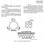
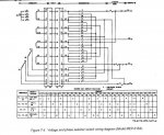
The procedure according to TM 5-6115-275-35 wants you to test for continuity between pins 3 to 6, 8 to 12, 7 to 10, 1 to 4, 2 to 5, 11 to 13 (field flash) and 9 to 14.

The same procedure according to TM 5-6115-275-14; pins 10 to 7, 4 to 1, 6 to 9, 14 to 3, 8 to 5, 2 to 12 and 11 to 13 (field flash).

The drawings in the -14 TM agree with the test procedure in that manual.

The -14 version is not correct from the measurements I have made.

The images below are from the -14 TM and would not be correct, unless someone else can explain the differences...
 

Attachments

DieselBob

Active member
2,891
13
38
Location
Arnold Maryland
Hello Bjorn. If it would help I could check the ohm readings on my set. I assume :roll: these measurements are taken at the Large connector on the cable that connects the control cube to the generator head.
 

cranetruck

Moderator
Super Moderator
Steel Soldiers Supporter
10,350
75
48
Location
Meadows of Dan, Virginia
Hello Bjorn. If it would help I could check the ohm readings on my set. I assume :roll: these measurements are taken at the Large connector on the cable that connects the control cube to the generator head.
Yes, thanks, it may be a helpful confirmation of my readings. On my set, the windings terminated on pins 2, 5, 8 and 12 are all shorted and should be two separate non-connected windings if I read the TMs right at all.
My previous posts on this subject are under the heading "MEP018 Field Flash question".

Looks like I need to take the generator head apart to see if the problem can be fixed easily or not.
 

PeterD

New member
622
6
0
Location
Jaffrey, NH
Any chance the leads out of the head are marked (would be 1-12 for the output leads)? The numbers are standardized (somewhat) and that may give you the 'clue' you need. The images you posted seemed to indicate that the manual writer was confused as to wire numbers and pin numbers, giving wire numbers when he meant to give pin numbers...
 

DieselBob

Active member
2,891
13
38
Location
Arnold Maryland
Bjorn, on my set pins 8 - 12 measure 0.2 ohms and pins 2 - 5 measure 0.3 ohms. measuring any other combination of these 4 pins read open. Sounds like you have a short in the to windings. I did take my readings at the plug that connects to the back of the control cube. Hope it helps.
 

cranetruck

Moderator
Super Moderator
Steel Soldiers Supporter
10,350
75
48
Location
Meadows of Dan, Virginia
Thanks Bob, much appreciated.

Again, I see the error in my ways of doing things (not looking at the details or overlooking the obvious), the pin numbers in Fig 8-7 refer to the J4 connector on the generator head NOT the connector at the control box end. It should be labeled J4 or P4 while the control box end should be labeled J1 or P1.

So, the test in the -35 TM relates to J1 (P1) while the test in -14 refers to J4 (P4).

Alright, if anybody is parting out a 10KW MEP018 genset, let me know, I'd be interested in the generator head as a back-up at the very least.
 
Last edited:
Top