• Steel Soldiers now has a few new forums, read more about it at: New Munitions Forums!

  • Microsoft MSN, Live, Hotmail, Outlook email users may not be receiving emails. We are working to resolve this issue. Please add support@steelsoldiers.com to your trusted contacts.


Trouble Diagnoising Glow Plug Controller

mijon

New member
55
0
0
Location
Fenton, MI.
A little Run Down:

I looked at the wiki under plug system for a Cucv M 1008. Used a Test Light and figured out 6 glow plugs where shot. Replaced the 6 gp's with new ones (Wellman 070). Truck is stock, no modifications. Turned on key, took about 45 seconds for the WAIT light to go out. I heard the "click" sound from the the relay before the wait light went out, then about 3 seconds later the WAIT light did go out. I then took a voltameter and checked voltage on the top terminal on the glow plug relay. It was reading voltage with the key OFF.

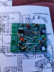
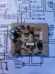
I'm thinking the problem is the glow plug controller. From what I read on the wiki if there is voltage present on the top terminal on the glow plug relay, with the key OFF, and if you hear a "click" sound from the glow plug relay with the key turned ON, your glow plug relay is okay. The problem is the operation should keep cycling (repeated "clicks" from the glow plug relay) and it doesn't. Which makes me think its the Glow Plug Controller. I watched the video "theory of operation video" in the stickies at the top of the forum. And what I took from it was that was the glow plug controller, cycles the whole operation.
1.WAIT light to
2.Controller CARD to,
3.Temp Sensor to,
4.Glow Plugs to,
5.The operation cycles again.
( Getting Proper Voltage from both Batteries)

Question:

My question is what do you guys think the problem is before I start throwing more money at? Can anyone point me the right direction with the TM's? I've read some on the Glow Plug Operation, but couldn't find anything on how to diagnose the GP Controller itself. Any thoughts or information would help me out a lot.
 

Warthog

Moderator
Super Moderator
Steel Soldiers Supporter
13,775
227
63
Location
OKC, OK
Did you read the TM 9-2320-289-20 tech manual of how to test the wiring and switchs for the GP controller? It is chapter 2-15 of the electrical troubleshooting section.
 

Crash_AF

Active member
1,530
7
38
Location
Colorado Springs, CO
Ok, top and bottom are relative to how you have your GPR installed. So we'll just go with the, 'from the resistor bank', and 'to the glow plugs' designation. Should be easy for you to track down.

There should always be 24V going to the post on the relay from the resistor bank if the batteries are charged and connected.
When you turn on the ignition and the wait light comes on, you should get a solid clunk from the relay engaging.
You should now have voltage on both large terminals on the relay
Voltage should drop to ~14v within a short time as the glow plugs heat up
The relay should clunk again after a period of time and voltage to the glow plugs should go away and voltage from the resistors should go back to ~24V
System will cycle the plugs after a period of time to keep them hot

Does that help any?
 

mijon

New member
55
0
0
Location
Fenton, MI.
Crash, thanks for the advice. Ive got 24 + volts with the top terminal on key off. Haven t Checked the voltage yet with key turned on for both terminals. I'm guessing there should be 12 volts in each terminal? There is no 2nd "thump" from the relay after some time. Why might that be? I think that's what my problem is, that 2nd "thump" doesn't sound. Is it safe to assume because there isnt a 2nd thump the GP operation isnt cycling.
 

Crash_AF

Active member
1,530
7
38
Location
Colorado Springs, CO
The second thump should be the relay opening back up. When it closes, you should have ~14 on both sides of the relay
If you have one of those remote starter triggers (the kind that clips to the starter solenoid to crank under the hood) you can jump the relay to test it without the controller card.
Hook one clip to a good ground, the other to the small terminal on the relay with the blue wire.
The pink/black wire should have 12V on it
With the key off, you should have ~24V on the resistor side of the relay, 0 on the GP side.
Turn the key on with the blue wire disconnected from the GPR
Pull the trigger and you should hear a clunk as the relay closes, and the voltage should drop to ~14v if all plugs are working properly
Release the trigger and you should hear another clunk as the relay opens, and the voltage on the top should return to 24V
If while the trigger is pulled, you have more than 14V, you probably have bad glow plugs.
If while the trigger is pulled, you have less than 14V, you probably have bad batteries
If all works well with this test, your controller card circuit needs work.

Final note, I found an error in the TM when I was building my 1009. The small orange wire from the GP controller goes to the GP terminal of the relay, NOT the resistor side as shown in the TM.
If wired as the TM shows, the controller card will never cycle the relay because the sense wire will always have voltage on it. Threw me for a loop while testing my 1009's system. Worked fine in testing, but the card never cycled the relay. After tracing out the circuit and thinking about how the circuit was intended to work, it was obvious that the diagram was wrong.

Later,
Joe
 

mijon

New member
55
0
0
Location
Fenton, MI.
Found the problem!! Took a voltmeter to the top terminal of the GP Relay. Read 25.2 volts, turned the key on and read the volts on the bottom terminal, 0 volts. Ordered the relay online for about 13 bucks including shipping. Just put it on tonight and the system cycled perfectly. Happy its not the controller. Thanks for the help guys. Hope this thread can be help for others.

Any questions ask! Read a lot of info. on tracking this problem down.
 

2deuce

Well-known member
1,448
111
63
Location
portland, oregon
I would consider eliminating the resister and running 12 volts to the relay from the terminal block on the other side of the resister. If you have a poor connection or a bad glow plug the resister will not lower the voltage to 12 volts and give too much voltage to the remainder of your glow plugs and start killing those. As they burn out one by one the voltage increases to the remainder and they burn out even faster. That is why you had 6 go bad. Those last 2 probably had 20+ volts going to them, they would not have lasted much longer either. It was this domino effect. There is a side effect to this but I feel it outweighs short glow plug life. Another thing to check are the connections at the glow plug, make sure they are good and tight. Put on new connectors if necessary.
 

mijon

New member
55
0
0
Location
Fenton, MI.
Good tip deuce thanks. The only thing is I need the 24volts to power my blade and salter. Even with two good running batteries, my gen 2 light comes on after a while of plowing. What would I have to do to run only 12v to the bottom terminal? Disconnect one battery?
 

jmenende

Well-known member
447
364
63
Location
Puerto Rico
Ive got a similar problem. My relay will cycle constantly. It burned my original gpc and when i swapped it out for a new modern gpc it still does the same cycle. Im sure my gp are already bad sin it seems this goes one when driving and my warm light no longer turns on.
 

Attachments

Top
AdBlock Detected

We get it, advertisements are annoying!

Sure, ad-blocking software does a great job at blocking ads, but it also blocks useful features of our website like our supporting vendors. Their ads help keep Steel Soldiers going. Please consider disabling your ad blockers for the site. Thanks!

I've Disabled AdBlock
No Thanks