• Steel Soldiers now has a few new forums, read more about it at: New Munitions Forums!

  • Microsoft MSN, Live, Hotmail, Outlook email users may not be receiving emails. We are working to resolve this issue. Please add support@steelsoldiers.com to your trusted contacts.

Connecting MEP to house

Speddmon

Blind squirrel rehabiltator
Super Moderator
Steel Soldiers Supporter
4,640
28
38
Location
Cambridge, Ohio
BC

The situation you are describing is what the NEC would deem to be a "Non Separately Derived System" (Non SDS) installation. In your case what you would want to do is this.

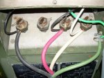
1) At the genset ground lug, disconnect the short wire coming from the plug on the back of the AC reconnection box from the grounding lug and tape it off. (This wire is your L0, Isolate it from ground)

2) Use your 4 wire cable just as you described above...hot wires to the breakers, neutral to neutral buss and connect the ground to the genset and the grounding location from your utility feed.

That's the safe way to do it according to the NEC. Read this thread...MEP-003a hook up question. It has a lot of information and even a few pictures of what I'm talking about with the Non SDS and why you want to isolate the ground and neutral from your genset.

The only problem with this type of installation is, if you ever want to use your genset as a stand-alone power source to power a welder or remote shop or something like that, then you'll have to hook up the L0 again and drive a ground rod to be able to use it safely.
 
Last edited:

tentpig

New member
2
0
0
Location
Boston
Sorry to reactivate old thread... Buddy of mine has lent me his MEP002A -- he has line power, I do not -- as the result of Hurricane Irene. His setup was installed by his brother-in-law, who is an electrican, whereas I'm "winging it" since this is a temporary setup for a week.

My connection point for the generator is my garage, which back-feeds into house about 75' away. My main breaker from the street is outside near the meter (required by code these days so the fire department can deenergize the house w/o pulling the meter). I already have that breaker off, and locked so nobody other than myself can access it, so no worries about trying to power up the neighborhood.

My question is how to properly connect the genset in the garage. Right now, the garage is fed by a 3-wire connection from the house -- neutral and 2 hots. There is no ground wire, nor is there a ground wire running from the garage electrical box to a separate grounding rod. (No flames please, it was this way when I bought the house). I believe the ground/neutral bus in the garage subpanel are bonded together anyway, since it appears some neutral and some ground wires are interchangably connected to the bonding strips for both anyway.

I'm using a 25' run on 6-3 w/ an 8awg copper ground, hard-wired into a 60-amp breaker. This is a temporary setup for a week until we get line power back... if it works, I may just go out and pick me up one of these toys for the future :)

Do I simply connect L0 to neutral, L1/L3 to hots, and ground to... what exactly?

I'm assuming I need to ground the genset since there is no ground from the sub-panel running back to the earth-ground on the house side.

If I had an earth-ground connection running from the garage to the house, I think this would be easier, it would just be a matter of decoupling L0 from the chassis ground, and then run the 8awg ground to the chassis, correct? But since I don't have that "4th" piece of wire running back to the house, I'm unclear as how to properly proceed.

Feedback appreciated, kids could use a nice hot bath tonite :)
 

mistaken1

New member
1,467
6
0
Location
Kansas City, KS
If you had all four wires to the garage you would connect L0 to the neutral, L1 an L3 to the phases and the ground to your generator frame ground and then remove the L0 to ground bond at the generator. You would also want to remove the bond from the neutral and ground at the garage panel.

Since someone ran only three wires to the garage they had to tie the neutral and ground together so that the grounding wires would have a path to ground.

This is not professional advice but considering what you have to work with I would say just connect the three wires as you have described and leave the generator L0-to-ground bond in place. Not the right way but it will provide a path to ground from the generator frame to allow the over current protection to work in case the frame becomes energized.

Check the house to see if the neutral (grounded conductor) and ground (grounding conductor) are bonded together. Then take a look at your grounding electrode system (ground rod, cold water pipe, etc.). Make sure you do have good grounding electrode system at the house.
 

tentpig

New member
2
0
0
Location
Boston
If you had all four wires to the garage you would connect L0 to the neutral, L1 an L3 to the phases and the ground to your generator frame ground and then remove the L0 to ground bond at the generator. You would also want to remove the bond from the neutral and ground at the garage panel.
Thanks for the reply. This is what I figured, but I wanted to check here with some "experts" first.

The panel in the house is wired correctly (separate neutral/ground busses) with an earth-ground connection -- I myself had that panel upgraded from 125 to 225 amps a few years ago, and I know the electrican who did the work did it to code as he pulled a permit and it was inspected by my town's electrical inspector. Everything was replaced from the pole to the panel inside the house. The garage panel I havent touched since I moved in.
 

PeterD

New member
622
6
0
Location
Jaffrey, NH
...
The panel in the house is wired correctly (separate neutral/ground busses) ...
just so that people in the future understand, some houses are wired with a combined neutral/ground bus. This configuration (was) acceptable when the house was built, and is considered acceptable today for existing construction (grandfather, so to speak) though for new construction a separate neutral and ground bus would be required. However, this bus is the only place where neutral and ground should be common.

To confuse things (much) more, many of these homes have the neutral/ground tie-in located in the meter box, not the breaker panel. That is, the wire coming from the meter designated as neutral is also the ground wire, meaning that it requires reworking of the meter connection to revise it to any configuration where the ground and neutral are combined into a single buss.

As an example, my house, built in the early 1980s, is configured that way--one buss bar, neutral/ground bonded at the meter, three wires coming into the box. Some day I'll replace the breaker panel and wire it to current codes, but that day may come after I die--considering how much I procrastinate and put things off!
 
Last edited:

mistaken1

New member
1,467
6
0
Location
Kansas City, KS
Thanks for the reply. This is what I figured, but I wanted to check here with some "experts" first.

The panel in the house is wired correctly (separate neutral/ground busses) with an earth-ground connection -- I myself had that panel upgraded from 125 to 225 amps a few years ago, and I know the electrican who did the work did it to code as he pulled a permit and it was inspected by my town's electrical inspector. Everything was replaced from the pole to the panel inside the house. The garage panel I havent touched since I moved in.

Then 2008 NEC lists an exception to that neutral/ground bonding. Based on my training it would be a good idea to have a grounding electrode system in your detached garage but we should consult the NEC to determine if it is required and how it should be built.

Attached is the entire 2008 NEC Article 250 Grounding and Bonding. The JPG file is the exception from Article 250.32.
 

Attachments

islandguydon

Well-known member
3,724
783
113
Location
Michigan
Ground, Ground, Ground..!

The first picture has no ground attached. #1 Ground the unit and #2 the new transfer switch to a new ground rod each. Use dielectric grease on the acorn nut and use a good copper rope.

All I can say is GROUND, GROUND, GROUND..! I just wired a 200A panel this past weekend.
 

Attachments

Last edited:

EO2NMCB

Member
643
22
18
Location
DeSoto, MO
The first picture has no ground attached. #1 Ground the unit and #2 the new transfer switch to a new ground rod each. Use dielectric grease on the acorn nut and use a good copper rope.

All I can say is GROUND, GROUND, GROUND..! I just wired a 200A panel this past weekend.
How can you tell from the pic where the ground (green) wire is going to? It could well be grounded to a rod for stand alone ops or to the genset for home hook up.
 

islandguydon

Well-known member
3,724
783
113
Location
Michigan
That green wire hanging should be grounded to the unit and the generator unit tied to a rod in the ground. At the house that green wire installs to the Neutral buss bar. The Buss bar is grounded to a rod the full 8' in the ground, unless your close to the water.

Here is a good example from the thread.
 

Attachments

EO2NMCB

Member
643
22
18
Location
DeSoto, MO
It was my understanding (from reading the thread) that you didn't want to ground to a grounding rod if you were hooking up to the house?
 

PeterD

New member
622
6
0
Location
Jaffrey, NH
It was my understanding (from reading the thread) that you didn't want to ground to a grounding rod if you were hooking up to the house?
It is not as simple as that... Issues include bonded neutral and if the generator is permanently connected or is not permanently connected. Regardless, it is not an error to ground with a grounding rod, the error is to not ground and then something happens and the generator chassis becomes electrically charged and then an accident happens. better two grounds than none, so to speak. Of course, none of this addresses the issues of bonded neutrals either!

If nothing else, refer to the NEC (edition that is being used at your location, or the latest edition) and you'll be set.
 

AndrewOH

New member
27
0
0
Location
Dayton, OH
I know this is a little old but I think that is important. There seems to still be a little confusion regarding grounding. Per OSHA's document liked to earlier, it says that you MUST connect it to a ground rod if connecting to the house. The only time you don't need to is when you are using appliances run only from a cord connected to the generator. However, a real ground (driven 8') is better than not having it regardless. The only places they don't necessarily like grounds are in high voltage substations because they are paths for very high fault currents to travel. Also, the neutral is not a ground even if it is grounded. When under a load, it carries current...

Big picture, keep it safe and ground that generator...


It was my understanding (from reading the thread) that you didn't want to ground to a grounding rod if you were hooking up to the house?
 

trukhead

New member
725
5
0
Location
dane/wi
I know this is a little old but I think that is important. There seems to still be a little confusion regarding grounding. Per OSHA's document liked to earlier, it says that you MUST connect it to a ground rod if connecting to the house. The only time you don't need to is when you are using appliances run only from a cord connected to the generator. However, a real ground (driven 8') is better than not having it regardless. The only places they don't necessarily like grounds are in high voltage substations because they are paths for very high fault currents to travel. Also, the neutral is not a ground even if it is grounded. When under a load, it carries current...

Big picture, keep it safe and ground that generator...
Thanks for contributing to the thread. I suspected the neutral carries current under load.

Before I start, a certified master electrician will be doing my install. With that.

I would like to use a 4 conductor for wiring to the transfer switch to the mep002.

Those being 2 conductors for L1 and L2 (hots), a third conductor for the LO (neutral), and a forth conductor as a tie in to the 8 foot ground rod at the transfer switch back through the wire to the ground lug on the generator. I may drive another copper rod for the generator for redundancy. Will that be safe?

The transfer switch will be more of a cut-out switch as the power comes in under ground, goes to the step down transformer then the meter then to breakers that do the house , shed , well pump, and barn. I just need to switch out the power company and connect to a receptacle that a cord from the generator will supply power to.

For running a possible future 3 phase machine I would use a 5 conductor cord that would use 3 conductors for 3 hots (L1, L2,L3), a neutral (LO) and a chassis ground to tie a copper ground rod driven into the ground for the genset and a tie in to the shop ground rod for the house.:idea:

I want it safe and correct so no one touches any thing and does this: :doghead:
 

ETN550

New member
457
9
0
Location
Knoxville, TN
A lot of 3 phase shop tools do not need or use a neutral. Stuff that is just motors like saws, lathes, mills, grinders, etc. Unless you need to have dedicated task lighting or you have certain lower voltage controls the neutral is not needed. Often, a second single phase line is run for 120 vac single phase lighting, etc. In a single phase circuit the neutral current is never more than the maximum in one hot leg and will be zero if both hot legs are equal, even if both legs are maxed out.
 

AndrewOH

New member
27
0
0
Location
Dayton, OH
I would like to use a 4 conductor for wiring to the transfer switch to the mep002.

Those being 2 conductors for L1 and L2 (hots), a third conductor for the LO (neutral), and a forth conductor as a tie in to the 8 foot ground rod at the transfer switch back through the wire to the ground lug on the generator. I may drive another copper rod for the generator for redundancy. Will that be safe?
Yes, a 4 conductor is the proper way to tie in your generator to your electrical system. I will do this and will also ground the chassis of my M103 separately just to be safe.

As for multiple ground rods, most cities seem to require two grounding rods at a minimum of 6' apart (otherwise, you must check the resistance of your soil to qualify for one). More is always better and grouding rods can go bad over time. I do not see any large scale problems with multiple ground rods even farther apart, especially if they are tied directly together. I called my local city electrical inspector to verify this and he said it does not violate the NEC 2008 (what we use here). The only problems I could see would be if lightning were to strike near the first rod and the second rod was in wetter soil (i.e. a better grounding point). You could get some current jumping across your grounding grid because the resistance of the soil would be higher than your copper. This is probably very doubtful (not to mention highly unlikely) and I don't think it would do too much damage even if this unlikely thing happened. Your electrical equipment has a small possibility of acting funny, too (the NEC recommends removing one ground and seeing if it fixes the problem).

I am doing exactly the same thing right now with my panel and will install multiple ground rods. Actually my lighting protection system (old house) is tied into my ground system and grounded at four other points. I'm not an electrician so please verify what I am saying, it is the best answer that I know of right now. You can also download the NEC 2008 for free if you search for it on the Internet. It has great information which I would suspect OSHA bases their information on.

Hope it helps...
 
Top
AdBlock Detected

We get it, advertisements are annoying!

Sure, ad-blocking software does a great job at blocking ads, but it also blocks useful features of our website like our supporting vendors. Their ads help keep Steel Soldiers going. Please consider disabling your ad blockers for the site. Thanks!

I've Disabled AdBlock
No Thanks