• Steel Soldiers now has a few new forums, read more about it at: New Munitions Forums!

  • Microsoft MSN, Live, Hotmail, Outlook email users may not be receiving emails. We are working to resolve this issue. Please add support@steelsoldiers.com to your trusted contacts.


MEP-803A - Quad fuse blows when increase of Voltage

Raphael

New member
12
0
0
Location
Carrollton/Ohio
Hi - This is my first post!!! Please be patient - I'm not yet up to speed:).

OK, we bought 2 MEP-803A, one runs fine, the other doesn't. Here is what happened:

I started the engine up and for about 10 sec. the voltage was normal and the frequency showed around 60Hz. Then the voltage dropped to 0V and the frequency went all the way down (I mean the Hz meter). I found, that the quad fuse was blown.

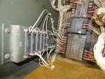
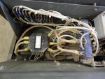
Since then I changed the frequency module A7 and the voltage regulator (we have 2 gen-sets) but it didn't help. I can change the fuse and it works for some time. The frequency keeps at the lowest setting at the meter. I found out, that the quad current is around 1Amp at 220V (L1-L3) (I run the unit at 120/240) but it increases very much when I do want to get up to 240V, where it should be. It is around 5A or higher. It seems that somehow the generator doesn't reach the output voltage and the voltage regulator cranks up the current, until the fuse blows.

We had a 3kW heater connected to it and it worked. Only I can't get up to 240V without the fuse blowing.

Here is another strange thing about the generator. I can measure a current at each of the wires coming out of the generator head without anything connected to it. Around 0.4-0.5A. I don't know where this goes - or is it reactive?

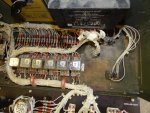
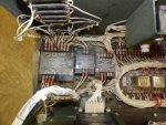
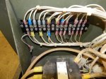
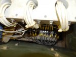
The generator was somehow modified. The diagnostic outlet was changed for a remote monitor outlet. (The diagnostic plug dangles inside...). There is written that before starting the remote monitor cable or the loop back plug should be attached. And there is a modification at the voltage reconnection switch. Where normally is the position for 220/208 and 120 is written do not use and at the 120/240 position is written: shadow CGS. I have no idea, what that is about.

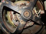
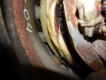
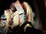
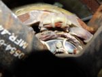
And it may be good to know, that the generator housing is damaged. It somehow fell at some time. Maybe that is important too?

I would appreciate any kind of help.

Thank you!
 

smokem joe

Active member
500
66
28
Location
Green OH
Sounds like you have a unit from Tobyhanna. I've had several with those modifications on them. Someone else might have an idea on why that fuse blows. I just know from experience the modifications you are talking about. It is all easy enough to remove and put back to stock if you want to
 

Raphael

New member
12
0
0
Location
Carrollton/Ohio
Thank you, AfghanVeteran2010. As the fuse blows again, and as the A1 seems to be good (it worked in the other unit), it seems that the stator is shot. Later I'll do some more testing...
 

Raphael

New member
12
0
0
Location
Carrollton/Ohio
OK, here are more details. I did the measurements according to the VR test sheet.

Quad circuit has 0.9 Ohm. I wouldn't rely too much on that, as it is a very low resistance, therefore there could be a high tolerance, but it somehow is where it should be.

Now the voltage measurements. I measured at 210V (L1-L3) because if I go higher, then the fuse would blow again.

Quad circuit (A1: Pin7 and 8): 68VAC (should be 68.2VAC)
VAC sense (A1: Pin3 and 4): 101.4 (should be 117.5 - but that's just related, with the measurement at lower voltage.)
Voltage adjust (A1: Pin 1 and 2): practically 0V (I had the potentiometer all the way down, so it does make sense.) (should be at 1.2VAC - it gets there, if I move the potentiometer to higher voltage output.)
Exciter field (A1: Pin 3 and 4): 18.5VDC and 29VAC. (Should be at 6.0VDC)

With that last measurement it seems to me, that we found the error. There seems to be an interruption at the exciter. Some problem with the brush, some oxidation or something else. That explains the high current at the quad circuit. The voltage regulator has to overcome the "negative" portions of the alternating current. Practically the whole AC part is not producing - it negates itself. But yet all the AC part needs and uses also current, so to say. This explains also the erratic frequency reading. If the exciter field is interrupted, then the frequency can't be 60Hz.

So, what should I do?

1. Just let it run without quad fuse, that the resistance may be brushed off? (Maybe the genset has been sitting for a long time and created oxidation?)
2. Spray contact spray somewhere?
3. adjust something somehow? (As I mentioned, the genset somehow fell (enclosure is bent). Maybe something got out of alignment.

I would appreciate any help.
Thank you.
 

Raphael

New member
12
0
0
Location
Carrollton/Ohio
OK, here are more details. I did the measurements according to the VR test sheet.

Quad circuit has 0.9 Ohm. I wouldn't rely too much on that, as it is a very low resistance, therefore there could be a high tolerance, but it somehow is where it should be.

Now the voltage measurements. I measured at 210V (L1-L3) because if I go higher, then the fuse would blow again.

Quad circuit (A1: Pin7 and 8 : 68VAC (should be 68.2VAC)
VAC sense (A1: Pin3 and 4): 101.4 (should be 117.5 - but that's just related, with the measurement at lower voltage.)
Voltage adjust (A1: Pin 1 and 2): practically 0V (I had the potentiometer all the way down, so it does make sense.) (should be at 1.2VAC - it gets there, if I move the potentiometer to higher voltage output.)
Exciter field (A1: Pin 3 and 4): 18.5VDC and 29VAC. (Should be at 6.0VDC)

With that last measurement it seems to me, that we found the error. There seems to be an interruption at the exciter. Some problem with the brush, some oxidation or something else. That explains the high current at the quad circuit. The voltage regulator has to overcome the "negative" portions of the alternating current. Practically the whole AC part is not producing - it negates itself. But yet all the AC part needs and uses also current, so to say. This explains also the erratic frequency reading. If the exciter field is interrupted, then the frequency can't be 60Hz.

So, what should I do?

1. Just let it run without quad fuse, that the resistance may be brushed off? (Maybe the genset has been sitting for a long time and created oxidation?)
2. Spray contact spray somewhere?
3. adjust something somehow? (As I mentioned, the genset somehow fell (enclosure is bent). Maybe something got out of alignment.

I would appreciate any help.
Thank you.
 

DieselAddict

Well-known member
Steel Soldiers Supporter
2,481
1,878
113
Location
Efland, NC
Even though your resistance measurement suggests the stator is ok the voltage and blowing fuses suggest it's not. I would lean towards believing the latter more than the former being the case. I recommend doing more testing of the stator. Get a meter that can accurately test it and check to see if it is shorted to the chassis.

This is is a brushless alternator so there is none of those kind of parts to cause issues. Based on your description it seems like the stator is damaged. :(
 

Guyfang

Moderator
Staff member
Moderator
15,843
22,005
113
Location
Burgkunstadt, Germany
OK, we need to do some ground work here.

OK, here are more details. I did the measurements according to the VR test sheet.

Quad circuit has 0.9 Ohm. I wouldn't rely too much on that, as it is a very low resistance, therefore there could be a high tolerance, but it somehow is where it should be.

Now the voltage measurements. I measured at 210V (L1-L3) because if I go higher, then the fuse would blow again.

Quad circuit (A1: Pin7 and 8): 68VAC (should be 68.2VAC)
VAC sense (A1: Pin3 and 4): 101.4 (should be 117.5 - but that's just related, with the measurement at lower voltage.)
Voltage adjust (A1: Pin 1 and 2): practically 0V (I had the potentiometer all the way down, so it does make sense.) (should be at 1.2VAC - it gets there, if I move the potentiometer to higher voltage output.)
Exciter field (A1: Pin 3 and 4): 18.5VDC and 29VAC. (Should be at 6.0VDC)

With that last measurement it seems to me, that we found the error. There seems to be an interruption at the exciter. Some problem with the brush, some oxidation or something else. That explains the high current at the quad circuit. The voltage regulator has to overcome the "negative" portions of the alternating current. Practically the whole AC part is not producing - it negates itself. But yet all the AC part needs and uses also current, so to say. This explains also the erratic frequency reading. The erratic freq reading, is because the voltage doesn't work right. The frequency meter uses AC voltage, (that is fed to a transducer) to give you the frequency. If the exciter field is interrupted, then the frequency can't be 60Hz. The exciter, is meant to light the main generator off. To give it initial excitation. That's on pins 5&6 of the A1. The exciter works. The gen set starts, comes up to normal voltage. So the exciter may not be the problem. Its possible, that the sensing voltage, pins 3&4 on the A1 are getting the wrong voltage. And if I am not wrong, that voltage comes from S8.

So, what should I do?

1. Just let it run without quad fuse, that the resistance may be brushed off? (Maybe the genset has been sitting for a long time and created oxidation?) What brush? This gen set is a brushless model. DO NOT RUN THE SET WITHOUT THE QUAD FUSE. Its there for a reason.
2. Spray contact spray somewhere?
3. adjust something somehow? (As I mentioned, the gen set somehow fell (enclosure is bent). Maybe something got out of alignment. Give us a picture. Then take the control panel door and top panel off, so you can look into the control cube, AND the compartment behind it. Look for something broken off, hanging loose down onto the TB, (terminal board). Then remove the mod. You don't need it, it will not work right for you, unless you have other parts that are not on the gen set, and you cant get. So get rid of it. Its an easy replacement. There is a thread here in SS that covers it, but if you take your time, and pay attention, you should be able to do it without a problem. And if this thing is improperly installed, it might just be your problem. Can you read schematics? What setting is your S8 and S6 in?

I would appreciate any help.
Thank you.
Clear the decks with getting rid of the mod first.
 

Raphael

New member
12
0
0
Location
Carrollton/Ohio
Thank you DieselAddict. I did some reading on brushless alternators and now I understand better...

No, none of the windings are shortened to the chassis. Quad as well as the other 6. The stator main windings I measure around 0.1Ohm between the contacts, but infinite to chassis.
 

Kenny0

Active member
121
30
28
Location
Leland, Iowa
Are you disconnecting the windings before measuring the resistance? Some meters will not measure very low ohms accurately. Borrow a meter that uses a four wire resistance reading for the most accurate measurement or check your meter with a known low resistance of 5 ohms or less. Does this generator have the MOV mod on the regulator? If it does it could have a defective MOV. Like others have said remove the tobyhanna mod.
 

Raphael

New member
12
0
0
Location
Carrollton/Ohio
Here some news:

1. I removed the Tobyhanna mod. It was very easy to do. But it didn't change anything.

2. There is no mov installed. It should be at the A1 between pins 7 and 8 - right?

3. I measured with the same ohm meter the main stator winding of a working generator and it also shows 0.1 Ohm.

4. S6: L3-L1/1 Phase; S8: 120V/240V

It may be the stator, but we can't deduce that from the resistance readings. What makes me suspicious about the stator is, that there is current flowing in the wires to the generator without any load. On the other hand, with S8 in 120V/208V mode (3 phases) there is exactly the same voltage on each leg.

Later today I want to post some pictures.
 

Guyfang

Moderator
Staff member
Moderator
15,843
22,005
113
Location
Burgkunstadt, Germany
Disconnect the main gen wires from the TB3. Then measure ohms. Also, check things out in there, to see if you have anything wrong/broken.

DO NOT, repeat, DO not, unhook wires and mark them with tags or with a sharpie. DO, repeat, DO, hook things back up using the schematic. If you cant read the schematic, due to it being a crappy copy, let me know. Also, there is a file in the SS forum section with enlarged schematics. Much nicer to work off of, but again, crappy quality pictures.
 

Raphael

New member
12
0
0
Location
Carrollton/Ohio
Thank you for all your help.

I uploaded a bunch of pictures. (TB3 still disconnected.)

I disconnected the main gen cables from TB3. I measured with several multi meters and it is consistenly 0.1-0.3 ohm.

The main windings don't look bad. I'm certainly not an expert, but it doesn't look burned. The winding of the exciter (That what it probably is, in the front) looks darker. Maybe there is a problem.
 

Attachments

jamawieb

Well-known member
1,412
511
113
Location
Ripley/TN
Thank you for all your help.

I uploaded a bunch of pictures. (TB3 still disconnected.)

I disconnected the main gen cables from TB3. I measured with several multi meters and it is consistenly 0.1-0.3 ohm.

The main windings don't look bad. I'm certainly not an expert, but it doesn't look burned. The winding of the exciter (That what it probably is, in the front) looks darker. Maybe there is a problem.
So you have the old quad fuse modification. One question, are you using a 250v glass fuse with a time delay? Usually 3amps? Because if your not using the correct the fuse, it's going to blow as you described.
 
Top
AdBlock Detected

We get it, advertisements are annoying!

Sure, ad-blocking software does a great job at blocking ads, but it also blocks useful features of our website like our supporting vendors. Their ads help keep Steel Soldiers going. Please consider disabling your ad blockers for the site. Thanks!

I've Disabled AdBlock
No Thanks