• Steel Soldiers now has a few new forums, read more about it at: New Munitions Forums!

  • Microsoft MSN, Live, Hotmail, Outlook email users may not be receiving emails. We are working to resolve this issue. Please add support@steelsoldiers.com to your trusted contacts.


Please help me to detect wires

sirmax123

Member
40
8
8
Location
Kharkov, Ukraine
Hi!

Finally, I continue to work on the truck (there are many custom changes before I got it so it is not in stock)

Could you please help me to identify 2 wires on the picture? it is the left side of the engine. I do not see any sensors or places where they can be connected.
If it was added by the previous owner, please let me know.

They are NOT glow plug power, because I disconnected it before (I found glow plugs wires in a terrible state and need to replace it)

Thank you,
Max
 

Attachments

D6T

Well-known member
219
511
93
Location
Vermont
Well, where do they lead to?

Edit to add: went out and looked at my truck. Not sure which side is “left” as you describe. Forgive my level of knowledge being well below many on this site, but I see similar wires for what I believe are the temperature sensor and electric choke thingamajig on the carb.
 
Last edited:

Curtisje

Well-known member
Steel Soldiers Supporter
574
654
93
Location
Okinawa, Japan
Hi!

Finally, I continue to work on the truck (there are many custom changes before I got it so it is not in stock)

Could you please help me to identify 2 wires on the picture? it is the left side of the engine. I do not see any sensors or places where they can be connected.
If it was added by the previous owner, please let me know.

They are NOT glow plug power, because I disconnected it before (I found glow plugs wires in a terrible state and need to replace it)

Thank you,
Max
The green wire goes to the temperature sensor in the side of the head. I have removed mine and replaced with a mechanical temperature gauge. see pic
20200726_133546.jpg

The brown wire goes to the alternator. See pics
20200726_133534.jpg
20200726_133559.jpg
 

cucvrus

Well-known member
11,263
9,552
113
Location
Jonestown Pennsylvania
The green wire goes to the temperature sensor in the side of the head. I have removed mine and replaced with a mechanical temperature gauge. see pic
View attachment 807219

The brown wire goes to the alternator. See pics
View attachment 807220
View attachment 807221
You are a genius. Yes the choke wire would not fit on mine so I attached it to the alternator. That is a Tach pick up wire for the diagnostic connector under the dash on the drivers side.
 

sirmax123

Member
40
8
8
Location
Kharkov, Ukraine
The green wire goes to the temperature sensor in the side of the head. I have removed mine and replaced with a mechanical temperature gauge. see pic

The brown wire goes to the alternator. See pics

Thank you!

More answers - more questions!


As I can understand, the left alternator was replaced by another one taken from some Ukrainian track or tractor. Now I'm trying to identify it now.

So questions are:

1. Left Alternator cables

What small terminal on the alternator doing? On my truck, the small terminal is connected (via resistor? black ones near 12v terminal) to 12V terminal
And positive pole (big terminal of the alternator) is also connected to the 12V terminal on body
Please see the pictures.

I do not understand why it was done in this way and how it works.
Will check another end of the brown cable.


2. Temperature sensor cable.

I can't find a temperature sensor on the picture. Could you please explain to me where is it?
Temperature sensor on dashboard works, so it is for Glow Plugs control?

I do not have any Glow Plugs automation, it was removed by the previous owner, and now before starting the engine, I just press the button for a few seconds (ten ore more, depends on the temperature outside).
So do I need this sensor? Or can I use it to understand is glow plugs works?

And after all.
As far as I can understand, Glow Plugs are connected to 12V. So is it converted to 12V from 24V? Looks like relay is connected to 12V.
 

Attachments

cucvrus

Well-known member
11,263
9,552
113
Location
Jonestown Pennsylvania
Thank you!

More answers - more questions!


As I can understand, the left alternator was replaced by another one taken from some Ukrainian track or tractor. Now I'm trying to identify it now.

So questions are:

1. Left Alternator cables

What small terminal on the alternator doing? On my truck, the small terminal is connected (via resistor? black ones near 12v terminal) to 12V terminal
And positive pole (big terminal of the alternator) is also connected to the 12V terminal on body
Please see the pictures.

I do not understand why it was done in this way and how it works.
Will check another end of the brown cable.


2. Temperature sensor cable.

I can't find a temperature sensor on the picture. Could you please explain to me where is it?
Temperature sensor on dashboard works, so it is for Glow Plugs control?

I do not have any Glow Plugs automation, it was removed by the previous owner, and now before starting the engine, I just press the button for a few seconds (ten ore more, depends on the temperature outside).
So do I need this sensor? Or can I use it to understand is glow plugs works?

And after all.
As far as I can understand, Glow Plugs are connected to 12V. So is it converted to 12V from 24V? Looks like relay is connected to 12V.
I am afraid to answer any of these questions pertaining to that wiring harness. One incorrect wire crossed and poof there goes the entire truck. WOW. I am sad to see this hacked up harness.
 

sirmax123

Member
40
8
8
Location
Kharkov, Ukraine
I am afraid to answer any of these questions pertaining to that wiring harness. One incorrect wire crossed and poof there goes the entire truck. WOW. I am sad to see this hacked up harness.
Anyway, I have to fix it. I got it "as is" and nobody knows here how it should work

So my plan is
1. Disconnect all wires. (and make pictures on each step)

2. Replace all wires related to alternators and batteries with new. (old is not in a good state).
It should not be rocket science, but it is :)

3. Replace all wires related to glow plugs sub-system and understand how it should work.


And start the engine and see.
And only after battery charging works well continue with other parts of wires.

Thank you!
 

MarcusOReallyus

Well-known member
4,524
808
113
Location
Virginia
Going back to stock wiring is your best route, I think. The original truck had a hybrid 12v/24v system. 24volts are used for the starter and glow plugs, and 12volts for everything else.

This is why there are two alternators. One charges the front battery normally as a 12v system. There is nothing special here.

However, the driver's side alternator charges the rear battery, and is electrically isolated from the rest of the vehicle. It MUST be, or smoke happens! This alternator is "grounded" to the positive (+) terminal of the front battery. It CANNOT be grounded normally, either by wire or through its case, as is normally done. This generates the usual 12v, but it is ADDED to the 12v of the front battery, so at the + terminal of the rear battery there is 24 volts as measured to the vehicle frame (ground).

It's like stacking two flashlight batteries on top of each other. We take two 1.5 volt batteries and add them together to get 3 volts. If we want to charge them, we need two 1.5 volt chargers. One of them must be connected to each battery. The bottom one will have its - connected to the - of the bottom battery, and its + connected to the + of the bottom battery. The other must have its - connected to the - of the TOP battery, and its + connected to the + of the TOP battery.

Like this:

Batteries and alternators connections.PNG
 

Curtisje

Well-known member
Steel Soldiers Supporter
574
654
93
Location
Okinawa, Japan
Thank you!

More answers - more questions!


As I can understand, the left alternator was replaced by another one taken from some Ukrainian track or tractor. Now I'm trying to identify it now.

So questions are:

1. Left Alternator cables

What small terminal on the alternator doing? On my truck, the small terminal is connected (via resistor? black ones near 12v terminal) to 12V terminal
And positive pole (big terminal of the alternator) is also connected to the 12V terminal on body
Please see the pictures.

I do not understand why it was done in this way and how it works.
Will check another end of the brown cable.


2. Temperature sensor cable.

I can't find a temperature sensor on the picture. Could you please explain to me where is it?
Temperature sensor on dashboard works, so it is for Glow Plugs control?

I do not have any Glow Plugs automation, it was removed by the previous owner, and now before starting the engine, I just press the button for a few seconds (ten ore more, depends on the temperature outside).
So do I need this sensor? Or can I use it to understand is glow plugs works?

And after all.
As far as I can understand, Glow Plugs are connected to 12V. So is it converted to 12V from 24V? Looks like relay is connected to 12V.
20200727_061714.jpg
This is where the temperature sensor should be. I have replaced mine with a mechanical gauge.
 

sirmax123

Member
40
8
8
Location
Kharkov, Ukraine
Going back to stock wiring is your best route, I think. The original truck had a hybrid 12v/24v system. 24volts are used for the starter and glow plugs, and 12volts for everything else.

This is why there are two alternators. One charges the front battery normally as a 12v system. There is nothing special here.

However, the driver's side alternator charges the rear battery, and is electrically isolated from the rest of the vehicle. It MUST be, or smoke happens! This alternator is "grounded" to the positive (+) terminal of the front battery. It CANNOT be grounded normally, either by wire or through its case, as is normally done. This generates the usual 12v, but it is ADDED to the 12v of the front battery, so at the + terminal of the rear battery there is 24 volts as measured to the vehicle frame (ground).

It's like stacking two flashlight batteries on top of each other. We take two 1.5 volt batteries and add them together to get 3 volts. If we want to charge them, we need two 1.5 volt chargers. One of them must be connected to each battery. The bottom one will have its - connected to the - of the bottom battery, and its + connected to the + of the bottom battery. The other must have its - connected to the - of the TOP battery, and its + connected to the + of the TOP battery.

Like this:

View attachment 807272
Thank you for your explanation!

>Going back to stock wiring is your best route, I think.
yes, generally speaking, you are 100% right.
But in my situation it is almost impossible to order original parts - sellers do not want to send to Ukraine. And it is also not chap.
So I'm trying to use parts I can find locally for replacement.


>This is why there are two alternators. One charges the front battery normally as a 12v system. There is nothing special here.
Each alternator must have some kind of charging controller. Otherwise, the battery will be overcharged.
I'm not sure about correct English word for this part, the direct translation from Russian sounds like "Controlling Relay". It stops charging the battery if the voltage is over 14V (for 12V-based vehicles )

Here I do not understand where is this "Relay", (and it should be one for each alternator!)


After googling for a long time I found the circuit, but still more questions than answers.
Quality is not good I even can't read some part of it.


Sorry, my questions may look stupid here, especially when I'm using wrong words for parts names. :(

I'm trying to understand how it works and why it was done in this way, and if I can understand it I will be able to understand how to fix it without replacing everything.
 

Attachments

MarcusOReallyus

Well-known member
4,524
808
113
Location
Virginia
Thank you for your explanation!

>Going back to stock wiring is your best route, I think.
yes, generally speaking, you are 100% right.
But in my situation it is almost impossible to order original parts - sellers do not want to send to Ukraine. And it is also not chap.
So I'm trying to use parts I can find locally for replacement.
Understood. I think really the only odd part is the driver side alternator, which must be isolated from the vehicle frame. We call it, "isolated ground". A standard alternator can sometimes be converted to isolated ground.

Other than that, the glow plug resistor is going to be difficult to find, but many of us simply remove it anyway. You can read about that here and here. Not everyone likes the idea of bypassing the resistor, but if yours has been removed, you don't need to worry about it.


>This is why there are two alternators. One charges the front battery normally as a 12v system. There is nothing special here.
Each alternator must have some kind of charging controller. Otherwise, the battery will be overcharged.
I'm not sure about correct English word for this part, the direct translation from Russian sounds like "Controlling Relay". It stops charging the battery if the voltage is over 14V (for 12V-based vehicles )

Here I do not understand where is this "Relay", (and it should be one for each alternator!)
It's built in to the alternator on these trucks. In some vehicles, it's external. We call it a "voltage regulator".

After googling for a long time I found the circuit, but still more questions than answers.
Quality is not good I even can't read some part of it.

All of the manuals, including the wiring diagrams, are available on this site for free download. You can find them here.

I think you might find a better diagram in the "Helpful Threads" sticky, which is here.


Sorry, my questions may look stupid here, especially when I'm using wrong words for parts names. :(
No, they don't look stupid at all. These trucks are very different from most vehicles, and it takes a bit of study to understand them. No problem!

I'm trying to understand how it works and why it was done in this way, and if I can understand it I will be able to understand how to fix it without replacing everything.

Well, WHY it was done this way was to make this vehicle able to jump start other NATO 24v vehicles, or to be jumpstarted by them. HOW it works is described in very good detail in the Helpful Threads section. You will find very useful info there.

(y)
 

sirmax123

Member
40
8
8
Location
Kharkov, Ukraine
First of all, I'd like to say Thank You (and all people here on the forum) for a detailed reply.

I spent hours reading manuals, but the problem I still have is that I do not understand all terms and the dictionary gives me "generic" translation.

So I still have to ask some questions.

Other than that, the glow plug resistor is going to be difficult to find, but many of us simply remove it anyway. You can read about that here and here. Not everyone likes the idea of bypassing the resistor, but if yours has been removed, you don't need to worry about it.
As I see from the current wiring, resistors are already removed, and I have to live with it. But glow plugs will be my next step.


It's built in to the alternator on these trucks. In some vehicles, it's external. We call it a "voltage regulator".
On my VAZ (car build in USSR, 1985) it was external, so I expected to find the same on M1008


All of the manuals, including the wiring diagrams, are available on this site for free download. You can find them here.
I think you might find a better diagram in the "Helpful Threads" sticky, which is here.
Very helpful, thank you!


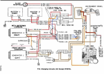
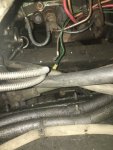
So, today I removed all protection from wiring and see how it is connected: (Please pay attention, Relay and blue wire it is not how it connected but how I expect it should be)

Charging Circuit  copy 2.png


And here I have some questions.

1. As I see, such alternator wiring should work.

Alternator 1 is replaced (from a bus, but do not know which one) and has 2 inputs

B+ - for battery connection
D - for Voltage Regulator
And Alternator 1 body operates as Negative Terminal (Engine Ground on this circuit I guess)

2. Problems I see here are:

- Now Voltage Regulator input is connected to +12V Terminal directly, without any relay. So "excitation winding" (not sure about English here) is always ON.
And as a result, Battery 1 (Front) is discharging. That I really have, and it was a reason why I started my wiring rebuild.

- If the green link removed and blue is enabled, it should be fixed.


3. But I do not understand how the control lamp and voltage regulator should work for Alternator 2 (Passenger Side).
Cold you please help me to understand how voltage regulation and control lam works for Alternator 2?

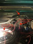
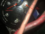
On pictures below, you can see how it really looks, And I do not understand what is "Black Cylinder" on this picture?
I see such near 12V and 24V terminals for multiple wires but I have never seen such before.


IMG_9087.JPG

Passanger_Side_Alternator-edited.jpg


Thank you,
Max.
 

sirmax123

Member
40
8
8
Location
Kharkov, Ukraine
I continue working on the truck, and have some more questions:

1. I removed my instrument cluster and suddenly realized that it differs from what I see in Manual.

So it looks like it was replaced by the previous owner. Is it correct?


IMG_7456.JPG


2. So, the next step is to find how wires are connected.

I found 3 sensors. 2 is on Engine, driver side

1 is on transmission

IMG_1813.JPG


Could you please help me to finde information about sensors?

On picture sensor with red wire looks like it was replaced.


Thank you,
Max
 

mike634

Member
Steel Soldiers Supporter
91
33
18
Location
Sussex New Jersey
Definitely not CUCV gauges. Starting at the upper left, the upper two spots should be the four wheel drive light with the oil pressure light next to it. The bottom two are the GEN 1 and Gen 2 lights.
 
Top
AdBlock Detected

We get it, advertisements are annoying!

Sure, ad-blocking software does a great job at blocking ads, but it also blocks useful features of our website like our supporting vendors. Their ads help keep Steel Soldiers going. Please consider disabling your ad blockers for the site. Thanks!

I've Disabled AdBlock
No Thanks