
Toddbo35
Member
- 41
- 62
- 18
- Location
- Hitchcock, Texas
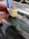
Easy fix. The purple with white trace is 12 volt from ignition switch. Solid purple is solenoid output 24 volt to starter. Red is 24 volt supply. This red wire is protected by a fusible link at the 24 volt bus, right side of firewall engine compartment. You need a wire to ground from the other coil terminal.
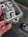
Well I got the doghead relay installed today. Motor spins over now. However I pulled the cover off the injection pump and just as you had mention the back screw was most definitely broken off. Spent a couple hours trying to get it out . Looks like I'm gonna have to drill it out.
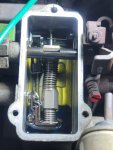
As far as the solenoids on the IP cover, they're both 24 volt. Not sure why I only have 12 volts supply to them. Another question I have is the glow plugs.......how much voltage should they have going to them when the relay is on?
Attachments
-
 50.3 KB Views: 13
 -
 49.6 KB Views: 13
 .
.