• Steel Soldiers now has a few new forums, read more about it at: New Munitions Forums!

  • Microsoft MSN, Live, Hotmail, Outlook email users may not be receiving emails. We are working to resolve this issue. Please add support@steelsoldiers.com to your trusted contacts.

MEP-002A Not producing power

Guyfang

Moderator
Staff member
Moderator
15,972
22,342
113
Location
Burgkunstadt, Germany
Open up TM 5-6115-584-34.
Turn to page 8-4, (Or PDF reader page #153)

h. Testing Generator Stator.
(1) High Potential Test. Test generator stator as
given in paragraph 8-2e of this manual. Replace
stator having faulty insulation.
(2) Winding Resistance Test. Perform winding resistance
test using a Kelvin bridge. Follow the manufacturer’s
instructions given on the bridge. Resistance
readings should be made on the pins of P9 and
P10 (see figure 8-3). Resistance between lead pairs
T 1- T4, T2- T5, T3- T6, T7- T1 0, T8- T11 and T9
- T12 should be 0.355 ± 0.036 ohms at 77°F (25°C). Refer
to the table in figure 8-3 for location of the terminals.
Also check resistance between each pin A through F
of P9 and P10 and the stator frame. Low resistance
indicates a shorted stator.
 

mtfleming

Member
68
16
8
Location
bristol, tn
Open up TM 5-6115-584-34.
Turn to page 8-4, (Or PDF reader page #153)

h. Testing Generator Stator.
(1) High Potential Test. Test generator stator as
given in paragraph 8-2e of this manual. Replace
stator having faulty insulation.
(2) Winding Resistance Test. Perform winding resistance
test using a Kelvin bridge. Follow the manufacturer’s
instructions given on the bridge. Resistance
readings should be made on the pins of P9 and
P10 (see figure 8-3). Resistance between lead pairs
T 1- T4, T2- T5, T3- T6, T7- T1 0, T8- T11 and T9
- T12 should be 0.355 ± 0.036 ohms at 77°F (25°C). Refer
to the table in figure 8-3 for location of the terminals.
Also check resistance between each pin A through F
of P9 and P10 and the stator frame. Low resistance
indicates a shorted stator.
Thanks so much for the information!
 

mtfleming

Member
68
16
8
Location
bristol, tn
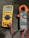
Thank you, would it be possible for you to post a picture of this ohm meter which will give me a better idea to explore some testing options for you?
I think somehow I uploaded it twice. Sorry it took so long for me to reply. All help is appreciated. I may be able to work on it some Monday.IMG_2765.jpeg
 
Last edited by a moderator:

mtfleming

Member
68
16
8
Location
bristol, tn
Guyfang said something about l have exciter voltage but the generator would not light off. I have checked resistances on stator and think they are okay. To check for a short I just connect one lead to body of gen head and other lead to each pin of J9 and J10? Since the exciter produces a little power at the convenience outlet, do you think maybe the problem is in the rotor? I wonder what a gen head would cost?

I don't know which pins are A-F in the instructions on reading them to ground, but I numbered the pins according to a diagram in the TM. Here are the results:

#1 9.9 ohms
#2 7.0 ohms
#3 0.8 ohms
#4-6 open
#7 9.8 ohms
#8 7.0 ohms
#9 1.0 ohms
#10-12 open

Are these good?
 
Top