

- 2,333
- 4,203
- 113
- Location
- Massachusetts
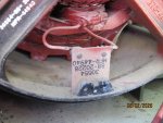
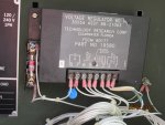
The image you posted is not the AC VR Test in the TM. That's a brief cheat sheet without the needed steps and conditions to correctly perform the tests.
The table of voltages listed on your sheet are approximately what one would measure IF the set was running, no load and outputting correct AC voltage.
Here IS the AC VR test procedure from the -24 TM...
Perform the steps and list the measurements for each measurement step.
For example..
Step h. 7.9 volts DC


")

