• Steel Soldiers now has a few new forums, read more about it at: New Munitions Forums!

  • Microsoft MSN, Live, Hotmail, Outlook email users may not be receiving emails. We are working to resolve this issue. Please add support@steelsoldiers.com to your trusted contacts.

P6 thrust bearing dodged a bullet…

Ronmar

Well-known member
4,368
8,245
113
Location
Port angeles wa
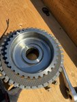
I am very glad I did this! Looked great inside, popped off the outer clutch pack snap ring and lifted out the clutch pack and carrier, discs and spacers look great. Center tower bushing, springs and piston look great, roller bearing looks OK until I try and lift it out.. The front/outer race and needle carrier lifted right off with no resistance leaving the inner race behind on the center tower…

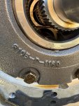
It was just a matter of time before the outer race and needle carrier popped forward off the inner race and down to rest on the carrier. Then the lip on the inner race and crimps that are supposed to hold it all together, would have methodically chipped away at the composite roller carrier until it released the rollers to thrash around in the clutch-pack and on into the rest of the transmission…

Whew!

Inner race is still on the center tower.

IMG_4153.jpeg


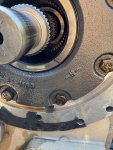
after I lifted out the thrust bearing inner race…

IMG_4154.jpeg
 

Plasa

Well-known member
Steel Soldiers Supporter
268
333
63
Location
Italy
Do you have a transmission that is affected by the Allison letter to change the bearing if transmission is before a certain serial number?
 

Ronmar

Well-known member
4,368
8,245
113
Location
Port angeles wa
All transmissions prior to ~Feb 2011(need to check s/n on the bulletin) are potentially affected by this...

Here is the basic chain of events. In the 90’s they produced with a particular p/n bearing, lets call it A. I think they knew about issues then, because even the military A0 LMTV manuals produced in the 90’s say to replace this bearing WHENEVER you are in the transmission/transfer case for any type of work.

At some point Allison officially acknowledged the failure with a tech bulletin stating that the type A roller thrust bearing should be replaced with a improved roller thrust bearing with a new P/N, lets call this one B… they also listed a s/n break point where production included bearing B.

At some point, I assume because bearing B was also failing or they suspected a possibility of failure, they issued a second tech bulletin directing that you replace bearing B with a composite thrust washer 3 times as thick as the A or B roller thrust bearings… that was feb 2011 and they again listed a S/N breakpoint where this new thrust washer was included in production…

I have no idea if a bearing B has ever failed, but Allison said replace it with a thrust washer for some reason, and they shifted production to the new thrust washer…

Here is a link to the most recent failure discussion. It has links to previous discussions and the tech bulletins…

 
Last edited:

NDT

Well-known member
Steel Soldiers Supporter
10,814
7,363
113
Location
Camp Wood/LC, TX
If you cut the bed away to allow cover removal, how many hours are we looking at to do this repair? Do we have to drain the fluid?
 

Ronmar

Well-known member
4,368
8,245
113
Location
Port angeles wa
it depends on your vehicle...
I believe you must drain the transfer, but that's the easiest part:) . You don't need to drain every last drop, just till the flow slackens near the end and put the plug back in, maybe 3.5 gal. (clean 5gal bucket, 3/8 drive ratchet or breaker bar, about 5 minutes)...

A 1078 you can trim the bed folded sheet metal crossmember. you can also unbolt the bed and lift the front 3-4" over the upper frame rail. Depending on your available tools and skillset, either will take perhaps an hour or longer. A plasma cutter would take perhaps 10 minutes to setup and cut out the interfering material... you need to be able to move the P6 clutch assembly~6" to the rear to slide the clutch center carrier off of the protruding center splined shaft...

There is a lower bolt-in crossmember in the main frame but it is far enough back to not be much of a factor except to reach around to access hardware or manipulate the assembly while lowering it out... not much of an issue...

If you have a 1079, get ready for the pain. I own a 1079 chassis... There is a heavy welded crossmember(same channel material the upper frame rails are made out of) in the upper frame, approximately 3" behind the P6... Besides having a m1079 box on top of it, it is huck bolted to the main chassis frame with 18-20 fasteners. you need to remove those fasteners and lift that upper frame rail ~8", or slide it 6" to the rear, to clear the P6 enough to remove it. The other option is to cut it out and turn it into a bolt-in crossmember... It is 1/4" 2" X 6" channel, so no easy task with the 1079 box in place, then prepping and drilling the remaining ends for a bolt plate or welding it back in...

Since I am converting that upper frame rail into my habitat floor, I did not want to cut that crossmember. but since I am making it a hydraulic captured spring habitat to chassis connection, I had already cut all the huck bolts out. I simply had to unbolt the front and lift the habitat floor and cargo boxes 8" to clear the P6.

Once the interferences are out of the way, Besides the 5 minutes to drain some oil, with a powered ratchet and a breaker bar, it is under an hour to remove all the hardware and pull off the p6 assembly(there is a notch on top to insert a screwdriver to pry/loosen the seal on the p6 cover, providing all the hardware spins out OK(15MM bolt heads, in 3 different lengths). It weighs ~55# but it is supported by the center shaft and a case guide ring, so you can get all the hardware out easily before you try and move it(nothing will freefall:)). not horrifically heavy and not until you slide it off the center shaft.

On the bench, 2 minute disassembly. Remove the upper/outer snap-ring with a screwdriver, and lift the center carrier and all the rotor and stator discs(perhaps 25#?) straight up and out of the housing and set aside to inspect later. That will leave you staring at the P6 thrust bearing on top of the tower like in the above pics...

Good luck if you should decide to accept this mission... This tape will self destruct in 5... 4... 3...
 
Last edited:

MatthewWBailey

Well-known member
Steel Soldiers Supporter
1,035
1,897
113
Location
Colorado
it depends on your vehicle...
I believe you must drain the transfer, but that's the easiest part:) . You don't need to drain every last drop, just till the flow slackens near the end and put the plug back in, maybe 3.5 gal. (clean 5gal bucket, 3/8 drive ratchet or breaker bar, about 5 minutes)...

A 1078 you can trim the bed folded sheet metal crossmember. you can also unbolt the bed and lift the front 3-4" over the upper frame rail. Depending on your available tools and skillset, either will take perhaps an hour or longer. A plasma cutter would take perhaps 10 minutes to setup and cut out the interfering material... you need to be able to move the P6 clutch assembly~6" to the rear to slide the clutch center carrier off of the protruding center splined shaft...

There is a lower bolt-in crossmember in the main frame but it is far enough back to not be much of a factor except to reach around to access hardware or manipulate the assembly while lowering it out... not much of an issue...

If you have a 1079, get ready for the pain. I own a 1079 chassis... There is a heavy welded crossmember(same channel material the upper frame rails are made out of) in the upper frame, approximately 3" behind the P6... Besides having a m1079 box on top of it, it is huck bolted to the main chassis frame with 18-20 fasteners. you need to remove those fasteners and lift that upper frame rail ~8", or slide it 6" to the rear, to clear the P6 enough to remove it. The other option is to cut it out and turn it into a bolt-in crossmember... It is 1/4" 2" X 6" channel, so no easy task with the 1079 box in place, then prepping and drilling the remaining ends for a bolt plate or welding it back in...

Since I am converting that upper frame rail into my habitat floor, I did not want to cut that crossmember. but since I am making it a hydraulic captured spring habitat to chassis connection, I had already cut all the huck bolts out. I simply had to unbolt the front and lift the habitat floor and cargo boxes 8" to clear the P6.

Once the interferences are out of the way, Besides the 5 minutes to drain some oil, with a powered ratchet and a breaker bar, it is under an hour to remove all the hardware and pull off the p6 assembly(there is a notch on top to insert a screwdriver to pry/loosen the seal on the p6 cover, providing all the hardware spins out OK(15MM bolt heads, in 3 different lengths). It weighs ~55# but it is supported by the center shaft and a case guide ring, so you can get all the hardware out easily before you try and move it(nothing will freefall:)). not horrifically heavy and not until you slide it off the center shaft.

On the bench, 2 minute disassembly. Remove the upper/outer snap-ring with a screwdriver, and lift the center carrier and all the rotor and stator discs(perhaps 25#?) straight up and out of the housing and set aside to inspect later. That will leave you staring at the P6 thrust bearing on top of the tower like in the above pics...

Good luck if you should decide to accept this mission... This tape will self destruct in 5... 4... 3...
Your theory in a previous thread was that the moving drive gear is heavy enough to slam into this thrust bearing when engaging 1. Is that perhaps the reason for the thick composite bearing?
 

Ronmar

Well-known member
4,368
8,245
113
Location
Port angeles wa
Now that I have had a chance to look at the setup with my own 2 eyes, there is nothing I can see that would push the carrier race back against the thrust bearing. The P6 piston pushes the disks forward and away from the thrust bearing, so the only possible effect would be to hold the carrier where it is at, as the discs bind together and apply load to the splines between case and carrier with torque applied… or, since the rotating discs ride on the carrier I believe it would tend to push the carrier race forward, away from the thrust bearing Before the disks, carrier and shaft bind together completely. I certainly don’t see it applying any bearing load…

Now it is possible that when the piston releases the discs, the whole assembly(carrier, rotors and stator discs, ~25#) could possibly rebound, or even be pulled slightly back toward the thrust bearing, by oil suction/surface tension on the piston face to the discs,

Force = Mass X Acceleration… i can pull the center carrier approximately 1/2” forward until it brings all the discs into contact/tension. If the acceleration is inertia related(vehicle movement) the shorter the distance it has to accelerate, the less energy it can deliver, so a taller bushing(.335”) would restrict it’s movement significantly… Even a gentle tap with a 25# sledge is a significant amount of energy...
 

87cr250r

Well-known member
1,361
2,120
113
Location
Rodeo, Ca
I don't know anything about this transmission but...

Roller bearings don't like to run unloaded. If there isn't a constant force pushing on them that can cause trouble. A plain bearing is just as happy loaded as it is unloaded.
 

Ronmar

Well-known member
4,368
8,245
113
Location
Port angeles wa
I don't know anything about this transmission but...

Roller bearings don't like to run unloaded. If there isn't a constant force pushing on them that can cause trouble. A plain bearing is just as happy loaded as it is unloaded.
Yep, I also think roller bearings probably don’t like being repeatedly accelerated by random contact and then released… this doesn’t bother plain bearings either:)
 

87cr250r

Well-known member
1,361
2,120
113
Location
Rodeo, Ca
The gentle tap with a big hammer is an interesting phenomenon. Some of my tugboats have a ~6" diameter 20' long solid steel shaft connecting the engine to the drive. The shaft uses split cylindrical roller bearings which use 10-32 screws to clamp the inner race to the shaft. They have a very limited axial load rating of around 5000lbs. Every once in a while one of these shafts slips forwards. Other companies have blamed some random phenomenon like incorrect warm-up of the engines. The reality is that the captains were hitting the ships too hard. With only a knot or so of speed that 2000lb hammer could generate a lot of force.
 
Top