• Steel Soldiers now has a few new forums, read more about it at: New Munitions Forums!

  • Microsoft MSN, Live, Hotmail, Outlook email users may not be receiving emails. We are working to resolve this issue. Please add support@steelsoldiers.com to your trusted contacts.

Sometimes the manual doesn't have all the answers

Summerpaws

Active member
48
146
33
Location
Hampton, NH
I have been faithfully reading this forum on a daily basis. You never know what tidbits you can pick up. My 802 has been flawless for over a year now. I've had 2 short outages in that time and it performed exactly as it should. I exercise it once a month using a 240 volt heater. I run it at 5000 watts for an hour. It's been exercised like this since I bought it. Never an issue. Today I walked by it while it was running and saw a red light. Overload. Obviously not an overload as the only load was the heater drawing 5000 watts. I reset S5 and reloaded it and it lasted all of 30 seconds before it tripped the overload. I was watching it and saw no abnormalities. So, I hit the TM's. I read on how to test K8, the overload/short circuit relay. I was planning on doing that tomorrow. Just for the heck of it, I decided to do a quick search on the forum for overload trips and I found a thread titled power output issues. In that thread there was a reply by kloppk where he explained how K8 works and then a very possible cause. Ray70 explained this on a related thread as well. So, this weekend I will Deoxit the heck out of the selector switch and the AM/VM switch and see what happens. I'll bet that it!

Thank you all for the wealth of knowledge. I'm retired from a power plant and can't get generators out of my blood.
 

Summerpaws

Active member
48
146
33
Location
Hampton, NH
The TM will point you in the right direction, but nothing beats the wealth of hands on knowledge available on this amazing site!
Good luck, clean and exercise the switches and test it again!
I agree. I was all set to do the test outlined in the TM but then I read the forum. I'm pretty sure this is the cause. It will run at 4000 watts for ever. Only when the load goes up does it trip the overload. Sounds like dirty contacts to me.. K8 looks like a sealed unit and the fact that it will take a 4K load and not trip kinda sounds like a connection rather than component failure. I live 1/4 mile from the ocean so I'm sure the air is salty when there's a sea breeze. Perfect for corrosion. I have a graduation party for my grandson tomorrow so I will try the fix on Sunday.
 

kloppk

Well-known member
Steel Soldiers Supporter
2,317
4,142
113
Location
Pepperell, Massachusetts
I'd suggest doing the following to narrow down if it's a K8 problem or a burden resistor or S6 or S8 switch contact issue.
Running is 120/240 mode apply your 5,000 watt load.
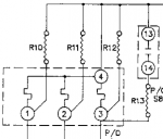
Then measure the AC voltage across K8 terminal pairs:
1 & 4
2 & 4
3 & 4
Each pair should have about 5.6 volts AC. This would be the expected AC voltage on them with a 5,000 watt load.
If you have about 5.6 volts or a bit less at each pair AND the Overload trips then you have a bad K8.
If find one or more pairs with way more than 5.6 volts AC then there is a burden resistor, S6 and/or S8 contact issue in that path.

1755964649313.png
 

Summerpaws

Active member
48
146
33
Location
Hampton, NH
I'd suggest doing the following to narrow down if it's a K8 problem or a burden resistor or S6 or S8 switch contact issue.
Running is 120/240 mode apply your 5,000 watt load.
Then measure the AC voltage across K8 terminal pairs:
1 & 4
2 & 4
3 & 4
Each pair should have about 5.6 volts AC. This would be the expected AC voltage on them with a 5,000 watt load.
If you have about 5.6 volts or a bit less at each pair AND the Overload trips then you have a bad K8.
If find one or more pairs with way more than 5.6 volts AC then there is a burden resistor, S6 and/or S8 contact issue in that path.

View attachment 952607
Thanks! I actually saw that on one of your posts. Very handy trick to know. Beats the 12 step procedure the TM has you do. Simple stuff first is always my mantra. More often than not, it solves the problem. I'll be in touch.
 

canadacountry

Well-known member
393
852
93
Location
Canada
@Summerpaws yeah I have to agree with @Ray70 as sometimes plain field experience literally beats textbooks, especially when its in the "hmm if you instead do ____" sort of way too

and not to make you chuckle too much while sorting your heater-running generator but heres a bit something from star trek below for you..
(not implying your generator can do much more but its a nice example of how sometimes textbook numbers don't always correspond to what the real numbers are when handled by someone who knew their things too well!)

la forge: the tank can't handle that much pressure
scott: where'd you get that idea?
la forge: what you mean, where did I get that idea? It's in the impulse engine specifications
scott: regulations 42/15: 'pressure variances in irc tank storage'?
la forge: yeah
scott: forget it. I wrote it. a good engineer is always a wee bit conservative, at least on paper. just bypass the secondary cutoff valve and boost the flow. It'll work.
 

Summerpaws

Active member
48
146
33
Location
Hampton, NH
@Summerpaws yeah I have to agree with @Ray70 as sometimes plain field experience literally beats textbooks, especially when its in the "hmm if you instead do ____" sort of way too

and not to make you chuckle too much while sorting your heater-running generator but heres a bit something from star trek below for you..
(not implying your generator can do much more but its a nice example of how sometimes textbook numbers don't always correspond to what the real numbers are when handled by someone who knew their things too well!)

la forge: the tank can't handle that much pressure
scott: where'd you get that idea?
la forge: what you mean, where did I get that idea? It's in the impulse engine specifications
scott: regulations 42/15: 'pressure variances in irc tank storage'?
la forge: yeah
scott: forget it. I wrote it. a good engineer is always a wee bit conservative, at least on paper. just bypass the secondary cutoff valve and boost the flow. It'll work.
Love it! My reputation at work was a guy who thought outside the box. It was one thing when we did maintenance, we did everything by the book. We had to. High voltage, natural gas at high pressure, high pressure steam. All deadly stuff. That said, when we had a breakdown with a sub system or some non critical component...often at 2am, I was usually the one to be called in because I could usually figure a way to MacGiver it back to operating status. It was my knowledge of how the system worked (and what the engineers said it would do) that allowed me to think outside the box and get it working. Just like Ray70 and Kloppk have done. They are familiar with these machines and how each component works that they can troubleshoot them in ways the TM just can't. I so appreciate that and understand their thinking.
 

LuckeyD

Well-known member
100
292
63
Location
Vilseck, Germany
Check your K8 and S8 and S6 like you say you will. Sounds like a plan. The S6 only switches to the front panel gages what you want to read as indicated on the front panel, and has nothing to do with your issue. If that circuit is working, leave it. Make it clean, cool stuff.

Just to think a moment about an area you have not mentioned; connect that 4KW load and after a warm up, apply that load. You say it will run forever that way. Now get a meter set to read AC Voltage. Measure the voltage on each active phase across the K1. (Phase L3 input to L3 output on the K1 for example) do you get a voltage drop? You shouldn't. If no drop go to the next item. If so, shut everything down, and do some K1 PM by burnishing those main contact pads inside. A Voltage drop increases your current draw and it gets worse with time, sometimes a very short time. In one class I had a 60KW 400HZ gen start the class all good and half way thru, it actually blew the top off the contactor. Turbine gens running you don't hear a lot. Usually contact pitting and sizzling shows up when loads are on when the K1 is engaged. Power companies use special circuits when applying power to a grid after an outage. The 802 has none. Minor pitting is normal.

The S8 does the same thing and is usually in place before starting the gen, but cleaning that puppy is a real pain. I usually moved the switch position several times until it stopped making any grinding noises while the gen was all OFF. One Soldier switched it while running once. Only once, Poof! Usually this does the trick setting contacts well together. I was successful in taking it apart and getting it back together again cleaning contacts from dirt , but you need patients. Lots of it. I was also among the few to do that. I do not recommend doing it so switching a little usually works. Cool?

The K8 is riveted together(some original K8s were screwed together), and is sometimes flakey in its operation. Most of the time you find it corroded inside and the coating on the inside resistors is flaking off from age and heat and I'll never know how the bugs get in there. External connections can also be no longer the best from vibration on an 802 and then the external relays could have issues. This and the The military uses wash racks and they never listened to "Don't Use that High pressure hose in there" . Old water intrusion is possible and you may also find condense water signs. Sometimes with an inch of water in the control box they tried to see if it still worked and after all it will dry better that way I was told, all was still wet; and then we usually got a call as it went Poof. Try your best and I believe you will be successful, just be safe. It would be nice to know what you found. Oh, also loose load terminals do the same thing, a loose connection does funny things. Overload is 110% so you are talking a new K8 will pop at 5, 500 watts, or supposed to . Some don't. If you ,after all the work, find nothing, (yes you will find something if only a fried bug and pitted contact points in the K1 or K8 inside resistor value change) and it functions well at 4000 watts on running, you still have a great gen and it also keeps things working well testing it at 4000 watts if you have to wait a while to obtain a good K8. TQGs were designed to run at over 70% load but no more than 90% allowing room for inductive reactance allowing the heater fan to turn on. A 5000 watt pure resistive load, is at the top. As parts get older they may no longer be at 100%. Think, your glass only holds 15 ounces and the beer is at the brim, and making foam with a sip is still in the can to your 5000 watts. Will it still run your load as you require when the lights go out?
 

Summerpaws

Active member
48
146
33
Location
Hampton, NH
Check your K8 and S8 and S6 like you say you will. Sounds like a plan. The S6 only switches to the front panel gages what you want to read as indicated on the front panel, and has nothing to do with your issue. If that circuit is working, leave it. Make it clean, cool stuff.

Just to think a moment about an area you have not mentioned; connect that 4KW load and after a warm up, apply that load. You say it will run forever that way. Now get a meter set to read AC Voltage. Measure the voltage on each active phase across the K1. (Phase L3 input to L3 output on the K1 for example) do you get a voltage drop? You shouldn't. If no drop go to the next item. If so, shut everything down, and do some K1 PM by burnishing those main contact pads inside. A Voltage drop increases your current draw and it gets worse with time, sometimes a very short time. In one class I had a 60KW 400HZ gen start the class all good and half way thru, it actually blew the top off the contactor. Turbine gens running you don't hear a lot. Usually contact pitting and sizzling shows up when loads are on when the K1 is engaged. Power companies use special circuits when applying power to a grid after an outage. The 802 has none. Minor pitting is normal.

The S8 does the same thing and is usually in place before starting the gen, but cleaning that puppy is a real pain. I usually moved the switch position several times until it stopped making any grinding noises while the gen was all OFF. One Soldier switched it while running once. Only once, Poof! Usually this does the trick setting contacts well together. I was successful in taking it apart and getting it back together again cleaning contacts from dirt , but you need patients. Lots of it. I was also among the few to do that. I do not recommend doing it so switching a little usually works. Cool?

The K8 is riveted together(some original K8s were screwed together), and is sometimes flakey in its operation. Most of the time you find it corroded inside and the coating on the inside resistors is flaking off from age and heat and I'll never know how the bugs get in there. External connections can also be no longer the best from vibration on an 802 and then the external relays could have issues. This and the The military uses wash racks and they never listened to "Don't Use that High pressure hose in there" . Old water intrusion is possible and you may also find condense water signs. Sometimes with an inch of water in the control box they tried to see if it still worked and after all it will dry better that way I was told, all was still wet; and then we usually got a call as it went Poof. Try your best and I believe you will be successful, just be safe. It would be nice to know what you found. Oh, also loose load terminals do the same thing, a loose connection does funny things. Overload is 110% so you are talking a new K8 will pop at 5, 500 watts, or supposed to . Some don't. If you ,after all the work, find nothing, (yes you will find something if only a fried bug and pitted contact points in the K1 or K8 inside resistor value change) and it functions well at 4000 watts on running, you still have a great gen and it also keeps things working well testing it at 4000 watts if you have to wait a while to obtain a good K8. TQGs were designed to run at over 70% load but no more than 90% allowing room for inductive reactance allowing the heater fan to turn on. A 5000 watt pure resistive load, is at the top. As parts get older they may no longer be at 100%. Think, your glass only holds 15 ounces and the beer is at the brim, and making foam with a sip is still in the can to your 5000 watts. Will it still run your load as you require when the lights go out?
Thanks Lucky. Looking at my K8, it is riveted (of course it is). I'll do the KloppK test on it and see what's what. Good idea re: K1. I know all about voltage drop and resistance. Seen many a 120 volt outlet overheat due to poor contact as well as a 5200 volt disconnect that was reduced to slag when hit with a load spike. Even low voltage circuits aren't immune. Like I said, this problem didn't rear it's ugly head until this last test. Last month it ran at 5K for an hour with no issues. That's why I think it makes sense that it is a bad contact somewhere.

Realistically, on a typical outtage, my base load for the whole house is around 500 watts. If the A/C's are on that is still a small load. In the winter, it's not much more because I heat with a pellet stove with oil as a backup. Don't care about my electric water heater or clothes dryer but it is nice to be able to use the stove, oven, and microwave when needed. I can easily manage the load to keep it under 4K. I live in a 200 year old house with a dirt floor basement and I do get water in occasionally. When that happens, I have 3 sump pumps that have to run. That is the main reason I have the genset. It may only happen once a year, but when it does and the pumps don't run, ho expensive hoo boy can there be a lot of expensive damage.
 

Summerpaws

Active member
48
146
33
Location
Hampton, NH
I don't want to leave you hanging, wondering if I did the cleaning and testing. Being retired and on a fixed income, I supplement my meager pension with side jobs. I had an emergency call on Sunday that a friends power in her whole house was low. Dim lights and a loud humming from the microwave. I had her turn off the main disconnect and ran over. What I found was the neutral wire from the main disconnect to the neutral buss bar was discolored and partially melted. It also smelled hot. I was able to cut back the wire and install a new ring connector. I chased the treads on the buss bar, cleaned the connection point until it was shiny and used a new bolt with a star washer. That got her up and running. I then called an electrician friend who came over, checked my work, and looked at the breaker panel. We both agreed that the panel needed to be replaced. He did that yesterday. Unfortunately a lot of her appliances are toast. She contacted her insurer.

It's funny that just a day prior to this, we were talking about how a bad connection causes heat and all sorts of bad things.

I am back on the 802 this morning. Cover off, S8 and S6 Deoxit'd. I did a very thorough inspection and saw now obvious wire issues. No loose connections either. After lunch I'll fire it up with a 5K load and see what happens. I will also check for voltage drop on K1 and check input voltage on K8.
 

Attachments

Summerpaws

Active member
48
146
33
Location
Hampton, NH
Good Day: Your harness Pictures look pretty good! Nice, clean, and you should get readings about everywhere you want with that one. Gen control box and S8 area with TB4 really look good. Interesting what comes inside the K8.
I was pleasantly surprised the first time I took the cover off. No evidence of mice although there were two old mud dauber thingies. I retorqued any connections held on with nuts and took a screwdriver to all other connections. I did find one connection on K1 that took 1/2 turn. All others less than 1/4.

I'm going to fire it and load it at 5K shortly. If it drops out on overload, I will measure low voltage at K8 and voltage drop at K1.
 

BeStihl

New member
18
21
3
Location
Kentucky
Interested in your findings, these guys will have you on your way. Just yesterday I tested the K8 on my 803 to verify O/L & S/C by using the method in the manual. It has you disconnect exciter field positive #6 of A1 which makes the generator produce a small voltage (14.5V L-N & 25V L-L in my case) in 3phase. You are then instructed to apply this 14.5V from #1-4, 2-4, and 3-4 on K8 and close the contactor to see if you get an O/L. Next it instructs you to do the same using the L-L 25Vac on those K8 terminals to check for a Short Circuit alarm. This was a cool test considering you need no special equipment just some jumper wires.

At any rate I said this to say you probably do just have some dirty contacts on K1 or S8 which are applying a voltage somewhat higher than full load spec on K8 causing the O/L. Would be interesting to know what the voltage readings are at K8 like Kloppk suggests.
 

Summerpaws

Active member
48
146
33
Location
Hampton, NH
Ran the generator at 3K for 10 minutes. No issues. Then at 4K for 10. No issues. Finally at 5K. Overload tripped after 5 minutes. This after a thorough cleaning of S8 and S6 and a careful check of all wiring connections I could get to. I did check voltage drop loaded to 4K across K1. No drop so that's good.
Finally did the low voltage measurements on terminals 1,2,3 and 4 on K8. I got interesting readings.

Loaded to 3K.
Terminal 4 and 1....2.3v
Terminal 4 and 2.....2.3v
Terminal 4 and 3.....3.5v

Loaded to 4K
Terminal 4 and 1....3.2v
Terminal 4 and 2....3.2v
Terminal 4 and 3....6.8

Loaded to 5K
Terminal 4 and 1....5.6v
Terminal 4 and 2....5.6v
Terminal 4 and 3....9.6v

I saw this coming as I increased the load. I am going to assume it is R13 off of K8 that could be bad or contact at 13 and 14?

I will hit the TM's and see what the resistance is for R13 and Deoxit those contacts again.
 

kloppk

Well-known member
Steel Soldiers Supporter
2,317
4,142
113
Location
Pepperell, Massachusetts
Loaded to 3K.
Terminal 4 and 1....2.3v
Terminal 4 and 2.....2.3v
Terminal 4 and 3.....3.5v

Loaded to 4K
Terminal 4 and 1....3.2v
Terminal 4 and 2....3.2v
Terminal 4 and 3....6.8

Loaded to 5K
Terminal 4 and 1....5.6v
Terminal 4 and 2....5.6v
Terminal 4 and 3....9.6v

I saw this coming as I increased the load. I am going to assume it is R13 off of K8 that could be bad or contact at 13 and 14?
My money is on contacts 13 & 14. They are supposed to be closed in 120/240 mode putting R13 in parallel with R12. If they don't make good contact it'll cause the excessive voltages you are seeing between 3 & 4.

1756239402541.png
 

Summerpaws

Active member
48
146
33
Location
Hampton, NH
My money is on contacts 13 & 14. They are supposed to be closed in 120/240 mode putting R13 in parallel with R12. If they don't make good contact it'll cause the excessive voltages you are seeing between 3 & 4.

View attachment 952865
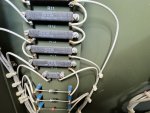
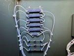
Makes sense. The chances of a resistor being bad is less than a physical switch. Looking closely at the resistors, is it me or does it look like someone has been in there? I will spend some extra time on the contacts for terms 13 and 14 and try it again.IMG_1751.jpegIMG_1753.jpeg
 

kloppk

Well-known member
Steel Soldiers Supporter
2,317
4,142
113
Location
Pepperell, Massachusetts
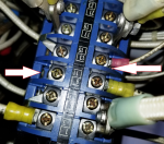
On S8 be sure to spray the Deoxit in the opening by each screw on both sides of S8.
This pic points out just two of the numerous spots to apply Deoxit.

You can see the contacts in S8 through the openings if there isn't a wire lug in the way such as the opening by the left arrow.
In that opening the contact is open. In the next opening down that contact is closed.

1756242061843.png
 
Top