• Steel Soldiers now has a few new forums, read more about it at: New Munitions Forums!

  • Microsoft MSN, Live, Hotmail, Outlook email users may not be receiving emails. We are working to resolve this issue. Please add support@steelsoldiers.com to your trusted contacts.

P6 thrust bearing dodged a bullet…

AdiBarbu

New member
26
7
3
Location
BC , Canada
Yep, Aluminum… Whats it going to do, void the warranty:) the Allison part looks like a fiber re-enforced thermoplastic, probably popped out of a injection mold machine run by Chinese slave labor for .50 each…

There is nothing I can find in this design that forces the clutch carrier back against the bushing. I think it only experiences casual intermittent contact…

Since the pressure lubricant flows in from the rear, around the end of the center shaft(past its bushing) and out the front of the center tower alongside the center shaft, the new thrust bushing that rests right at the front of the center tower is basically under a waterfall of lube oil. In fact when the center carrier race slides back to contact the bushing, the bushing will basically be pressure lubed as that space where disc carrier race contacts the thrust bushing is the only real way for the pressurized oil to leave the center tower except perhaps along the shaft splines… it will now be forced toward the oil notches/passages to be spread between thrust bushing and disc carrier race.

pretty certain it will last longer than I do:)

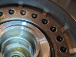
As for dimensions, well Allison was kind enough to provide the new bushing thickness, 8.5mm or .335”, in the second bulletin. Also that it is 4.9mm thicker than the original which was ~3.5mm…. The roller bearing is 1.992ID and 2.862 OD, but I am machining the bush to a slightly larger OD as the races it sets upon appear to be 2.920. so more oil film surface area to spread out the load.

only partial extra points as I can find no alloy stamps on the piece of 1/2” plate I have available… it drills and machines easy enough so it is not one of the harder alloys, but not as soft as plastic… I might be more concerned if there was some active load on this bearing and there wasn’t so much lube available. I do not expect much wear…
So a "washer" 0.335" thick with an ID of 1.992" and OD of 2.920" instead of that bearing ? Thanks
 

Ronmar

Well-known member
4,475
8,393
113
Location
Port angeles wa
You can get aluminum bronze plate 3/8 x 3 x 6(enough for 2 bearings) from Grainger for ~100… There are also a couple of marine thrust washer suppliers that make close dimensions 1-3/4ID to 3” OD but nothing that thick. They could be stacked and sweated/soldered then machined to the correct dimensions. The only critical one is the 1.992ID to create a tight fit on the center tower…
 

AdiBarbu

New member
26
7
3
Location
BC , Canada
You can get aluminum bronze plate 3/8 x 3 x 6(enough for 2 bearings) from Grainger for ~100… There are also a couple of marine thrust washer suppliers that make close dimensions 1-3/4ID to 3” OD but nothing that thick. They could be stacked and sweated/soldered then machined to the correct dimensions. The only critical one is the 1.992ID to create a tight fit on the center tower…
I will have them made out of tuffkast I think. I needed only the dimensions so I can replace in same day. Do you have by any chance a drawing with the original Allison bushing? Maybe some grooves for lubrication in there? Thank you.
 

Ronmar

Well-known member
4,475
8,393
113
Location
Port angeles wa
I will have them made out of tuffkast I think. I needed only the dimensions so I can replace in same day. Do you have by any chance a drawing with the original Allison bushing? Maybe some grooves for lubrication in there? Thank you.
No drawing, look back thru the transfer case discussions i linked to on the first page of this discussion. You will find pics of the Allison part there.. There is a single ~.06“ U/V profile channel groove in the middle of the face between the ID and OD (~.06” wide x .06” deep). There are 4 radial V grooves at 90 degree intervals running from ID to OD across the face. These are wider than they are deep ~.2”W x .06”D. This divides the face into 8 curved rectangles. These grooves are on both sides of the Allison part, with the 4 radial grooves offset 45 degrees from one face to the other…
 

AdiBarbu

New member
26
7
3
Location
BC , Canada
No drawing, look back thru the transfer case discussions i linked to on the first page of this discussion. You will find pics of the Allison part there.. There is a single ~.06“ U/V profile channel groove in the middle of the face between the ID and OD (~.06” wide x .06” deep). There are 4 radial V grooves at 90 degree intervals running from ID to OD across the face. These are wider than they are deep ~.2”W x .06”D. This divides the face into 8 curved rectangles. These grooves are on both sides of the Allison part, with the 4 radial grooves offset 45 degrees from one face to the other…
Thank you Ron.
This bushing I draw, looks right to you as dimensions please?PXL_20251007_200427505~2.jpg
 

CONJIN

Active member
87
122
33
Location
Northern California
You can get aluminum bronze plate 3/8 x 3 x 6(enough for 2 bearings) from Grainger for ~100… There are also a couple of marine thrust washer suppliers that make close dimensions 1-3/4ID to 3” OD but nothing that thick. They could be stacked and sweated/soldered then machined to the correct dimensions. The only critical one is the 1.992ID to create a tight fit on the center tower…
I've got some silicon bronze that I could throw on the lathe, but maybe too hard for this application?
 

AdiBarbu

New member
26
7
3
Location
BC , Canada
I am very glad I did this! Looked great inside, popped off the outer clutch pack snap ring and lifted out the clutch pack and carrier, discs and spacers look great. Center tower bushing, springs and piston look great, roller bearing looks OK until I try and lift it out.. The front/outer race and needle carrier lifted right off with no resistance leaving the inner race behind on the center tower…

It was just a matter of time before the outer race and needle carrier popped forward off the inner race and down to rest on the carrier. Then the lip on the inner race and crimps that are supposed to hold it all together, would have methodically chipped away at the composite roller bearing carrier/spacer every time the clutch carrier slid back against it, until it released the rollers to thrash around in the clutch-pack and on into the rest of the transmission…

Whew!

Inner race is still on the center tower.

View attachment 952296


after I lifted out the thrust bearing inner race…

View attachment 952295
My bushing is worn out.
Could you understand where the seal is made in the clutch? I couldn't get that other than maybe massive flow.
 

Attachments

Ronmar

Well-known member
4,475
8,393
113
Location
Port angeles wa
My bushing is worn out.
Could you understand where the seal is made in the clutch? I couldn't get that other than maybe massive flow.
So there was no thrust bearing in there at all like in the very first picture at the start of this thread? What does the back side of the center carrier look like?

The clutch piston is a ring shaped piston, its inner and outer seals are down below that disc with the holes and springs under it. I am not understanding your question… when pressurized the piston pushes that spring ring forward to compress the stacked rotating and stationary discs locking the center shaft to the outer case. If you9 look at the backside of the clutch housing, you will see 2 molded in passages. One feeds the center of the case, thats the lube oil. The other feeds the clutch piston. You can see where these two passages are fed around the edge of the housing. If you apply compressed air to the clutch feed port, you can observe the clutch piston movement/action…
 

AdiBarbu

New member
26
7
3
Location
BC , Canada
So there was no thrust bearing in there at all like in the very first picture at the start of this thread? What does the back side of the center carrier look like?

The clutch piston is a ring shaped piston, its inner and outer seals are down below that disc with the holes and springs under it. I am not understanding your question… when pressurized the piston pushes that spring ring forward to compress the stacked rotating and stationary discs locking the center shaft to the outer case. If you9 look at the backside of the clutch housing, you will see 2 molded in passages. One feeds the center of the case, thats the lube oil. The other feeds the clutch piston. You can see where these two passages are fed around the edge of the housing. If you apply compressed air to the clutch feed port, you can observe the clutch piston movement/action…
Thanks Ron. Now I understand how it works.
Everything else looks good. The trust bearing was there and if fair shape... little rust on it. Only the bushing worn out.
 
Top
AdBlock Detected

We get it, advertisements are annoying!

Sure, ad-blocking software does a great job at blocking ads, but it also blocks useful features of our website like our supporting vendors. Their ads help keep Steel Soldiers going. Please consider disabling your ad blockers for the site. Thanks!

I've Disabled AdBlock
No Thanks