- 10,882
- 814
- 113
- Location
- Appomattox, VA
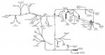
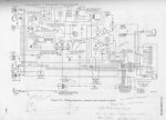
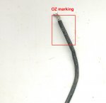
Does someone have a list of all the wire numbers in a deuce? I am trying to decode some wire numbers that are causing routing problems in my truck, would like to know what the numbers are supposed to be used for.