- 1,205
- 1,469
- 113
- Location
- Basehor, KS
If I read my TM correctly it should be TB 14 with D 13A connected to itIs that terminal 15, or 14?
Steel Soldiers now has a few new forums, read more about it at: New Munitions Forums!


If I read my TM correctly it should be TB 14 with D 13A connected to itIs that terminal 15, or 14?
A third fuse / 3rd phase is not really necessary for the following reasons:The other thing I wanted to ask you gentlemen is should I be running another fuse and bringing all three a/c lines to the new regulator? I’m planning on using this unit in its original configuration for three phase 208vac to power some hydraulic elevator equipment. I’m sure the regulator will work with two incoming a/c signals, but would it be better to connect all 3?
Copy that, and thank you once again. What an amazing resource this site is with the support and experience from members like yourself! I’ll update as soon I get finished up. Hopefully this evening.A third fuse / 3rd phase is not really necessary for the following reasons:
The ADVR 054 is a single phase Regulator
Terminals A and C are used for Voltage monitoring / regulation
Terminals B and C are used for the actual High Voltage Supply to power the ADVR
It is more important that the two phases terminate on Terminal B and C, as they draw the highest current and the jumper will then supply the phase connected to B to A as well via a Jumper.
The two Terminals B are connected on the circuit board directly
Remember, haste makes waste..............Copy that, and thank you once again. What an amazing resource this site is with the support and experience from members like yourself! I’ll update as soon I get finished up. Hopefully this evening.
Guy ( @Guyfang ), thanks, I checked here as well after the question was posted. Most people never bother looking at them, even when they got the doors open.If I read my TM correctly it should be TB 14 with D 13A connected to it
When in doubt, look at the MEP-005A TM. Some of the TM's are very old and copied too often, they are hard to read. BE ADVISED, the 15 & 30 KW TM's are very well known for having mistakes in the Schematics.


Wait a minute, I think I do see it at the relay board terminal. Right here.I’m k I’m back at n here looking at this. The terminal strip on made the A5 is going to be difficult to access. I’m I looking at the diagram correctly thinking that wire D118 will n the A11 J9 connector is the same wire? Looks like it is going thru R35 and then to the J9 connector. Can I intercept the wire there for simplicity?
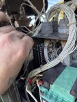
You can use the wire D11B which terminates on Pin C of P9Wait a minute, I think I do see it at the relay board terminal. Right here.
You can use the wire D11B which terminates on Pin C of P9
This would leave R35 in the circuit but that should give you still enough voltage for excitation
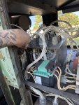
guessing a terminal number is never a good idea. If you want to connect to A5 TB14 then make 100% sure that you are on A5 TB14
otherwise you may experience fireworks beyond your wildest imagination


 . Couple minor issues, first, the wire from terminal 14 in the A5 produces 27 volts dc but it won’t carry any current. When I connect that to the completed circuit it will read voltage to the incoming side of the resistor but nothing to the other side. When I disconnect that wire and jump it to the d/c breaker the excitation gets going and the output is working. Now the main breaker isnt closing with the switch so I need to get into that. I had it working before so it’s something intermittent there. I suppose I can just revert back to the field flash button on had already installed but I’m m puzzled as to why the terminal 14 won’t work now.
Nice job! Looks good!Alright quick update on this thing. I got busy with the kids sports but I was able to finish the install enough for a test. It’s producing power. Sorry to disappoint you fellas but no fireworks
We get it, advertisements are annoying!
Sure, ad-blocking software does a great job at blocking ads, but it also blocks useful features of our website like our supporting vendors. Their ads help keep Steel Soldiers going. Please consider disabling your ad blockers for the site. Thanks!