McKeelo
Member
- 35
- 52
- 18
- Location
- Upland, CA
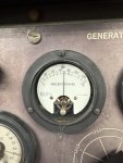
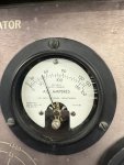
Is this the S9 switch? Is it difficult to repair?
Attachments
-
 1.9 MB Views: 3
Steel Soldiers now has a few new forums, read more about it at: New Munitions Forums!

Yes it is.Is this the S9 switch? Is it difficult to repair?
I guess the simple thing to do here is connect the manual flash button and move on but this thing is making me crazy nowAlright guys, here’s the update, I took the S9 switch apart even though I didn’t have any parts to replace anything with. Just took it apart for fun. Thank you to member Leedawg for posting the step by step run down. Everything looked ok, if I had a micro switch for s9-1 I would have replaced it. I probed around with the meter and in terminals a,b,and c everything meters the way I expected. The contacts are making and breaking the way they should. Every once in a while the normally closed contacts bounce around on the ohm scale quite a bit and I’m sure that’s the intermittent starter issue.
Now the exciter problem is another story. I found in the TM diagram that the k5 relay coil is terminal 13 on the A5 board and the normally open k5 contact is indeed terminal 14 as mentioned. When I jump 24dc Fromm the breaker to term. 13 I can hear the relay pick and I can meter the dc voltage on and off terminal 14 as intended. However when I start the generator terminal 13 and 14 both go high on start like they should but with S2 in the run position they both stay high +24vdc. I can’t figure out why? From the diagram it looks like the voltage should drop off with S2 in the run position, regardless of what S9-1 n/o and n/c contacts are doing. If I turn S7 on while running it does drop the voltage off A5 term. 13, and 14. I don’t see anything else that would keep the K5 relay coil voltage on with S2 in the run position. Any thoughts?

You have to check the wiring on the S2 switchAlright guys, here’s the update, I took the S9 switch apart even though I didn’t have any parts to replace anything with. Just took it apart for fun. Thank you to member Leedawg for posting the step by step run down. Everything looked ok, if I had a micro switch for s9-1 I would have replaced it. I probed around with the meter and in terminals a,b,and c everything meters the way I expected. The contacts are making and breaking the way they should. Every once in a while the normally closed contacts bounce around on the ohm scale quite a bit and I’m sure that’s the intermittent starter issue.
Now the exciter problem is another story. I found in the TM diagram that the k5 relay coil is terminal 13 on the A5 board and the normally open k5 contact is indeed terminal 14 as mentioned. When I jump 24dc Fromm the breaker to term. 13 I can hear the relay pick and I can meter the dc voltage on and off terminal 14 as intended. However when I start the generator terminal 13 and 14 both go high on start like they should but with S2 in the run position they both stay high +24vdc. I can’t figure out why? From the diagram it looks like the voltage should drop off with S2 in the run position, regardless of what S9-1 n/o and n/c contacts are doing. If I turn S7 on while running it does drop the voltage off A5 term. 13, and 14. I don’t see anything else that would keep the K5 relay coil voltage on with S2 in the run position. Any thoughts?
. I still need a couple little parts but this thing is almost ready to go into service.Easier said than done. Even more difficult on a shoestring budget. I haven’t had much luck finding any parts. I did find the missing enclosure door though. It ended up costing more in shipping than the door actually cost.Or you find a new S9.
 It works really good, haha