Alright, back for another attempt...
I made it through the entire electrical diagnostic section of TM 5-2420-244-20-1 and was not able to find any issues. I then at some point realized that "ignition switch", "engine start switch", and "starter switch" all refer to different things and was second guessing whether I had mistakenly swapped any of those three terms and did a test wrong, so I started over from scratch and went through everything again... still nothing.
I can only assume that I am doing one of these tests improperly because of the extreme vagueness that many steps seem to have (whoever said this process is easy to read/follow is out of your mind... as a retired 2W2, there's no chance we'd have made it through a single operation without shutting it down and submitting changes for a major TM revision).
Anyway, that brings me to step 4 on page 3-71
"Step 4. Disconnect connector D (3) and check for +24 VDC between wire 11 (4) and ground. If +24 VDC is not present, repair wiring 11 between starter and connector D. If +24 VDC is present, reconnect connector D and go to step 5."
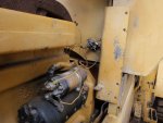
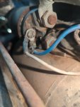
So, if I disconnect connector D there are obviously two pieces to the connector... one that's attached to the underside of the fuse boxes, and one that isn't. If I test the side that isn't connected, I do indeed get 24 volts. If I test the part of the connector that is attached to the bottom of the fuse boxes, I get nothing. Which side am I supposed to be testing?
I made it through the entire electrical diagnostic section of TM 5-2420-244-20-1 and was not able to find any issues. I then at some point realized that "ignition switch", "engine start switch", and "starter switch" all refer to different things and was second guessing whether I had mistakenly swapped any of those three terms and did a test wrong, so I started over from scratch and went through everything again... still nothing.
I can only assume that I am doing one of these tests improperly because of the extreme vagueness that many steps seem to have (whoever said this process is easy to read/follow is out of your mind... as a retired 2W2, there's no chance we'd have made it through a single operation without shutting it down and submitting changes for a major TM revision).
Anyway, that brings me to step 4 on page 3-71
"Step 4. Disconnect connector D (3) and check for +24 VDC between wire 11 (4) and ground. If +24 VDC is not present, repair wiring 11 between starter and connector D. If +24 VDC is present, reconnect connector D and go to step 5."
So, if I disconnect connector D there are obviously two pieces to the connector... one that's attached to the underside of the fuse boxes, and one that isn't. If I test the side that isn't connected, I do indeed get 24 volts. If I test the part of the connector that is attached to the bottom of the fuse boxes, I get nothing. Which side am I supposed to be testing?