• Steel Soldiers now has a few new forums, read more about it at: New Munitions Forums!

  • Microsoft MSN, Live, Hotmail, Outlook email users may not be receiving emails. We are working to resolve this issue. Please add support@steelsoldiers.com to your trusted contacts.

P6 thrust bearing dodged a bullet…

87cr250r

Well-known member
1,367
2,131
113
Location
Rodeo, Ca
An important characteristic of a plain bearing is galling resistance which aluminum does not have. Brass isn't so great either. Aluminum bronze would be a better choice. Plastics can work very well as they're able to be embedded with lubricants and are inherently resistant to galling. Plastics such as Nylon 4/6 can exhibit very long life as engine bearings. The Euros like Nylon 6/6 which is why their timing chain guides fail.

It doesn't have to be softer to make a good bearing.

This document is geared towards stainless steel bearings but the concepts are broadly applicable.


ckouba

Well-known member
Steel Soldiers Supporter
683
1,986
93
Location
Oregon
Yep, Aluminum… Whats it going to do, void the warranty:) the Allison part looks like a fiber re-enforced thermoplastic, probably popped out of a injection mold machine run by Chinese slave labor for .50 each…

...As for dimensions, well Allison was kind enough to provide the new bushing thickness, 8.5mm or .335”, in the second bulletin. Also that it is 4.9mm thicker than the original which was ~3.5m…. The roller bearing is 1.992ID and 2.862 OD, but I am machining the bush to a slightly larger OD as the races it sets upon appear to be 2.920.
So a donut 0.335" thick with an ID of 1.992" and OD of 2.920" of "soft-ish" alu or plastic is all that's needed?
 

Ronmar

Well-known member
4,395
8,303
113
Location
Port angeles wa
If it were a constantly loaded application I would not do it this way, but with the abundance of lubrication flow and only casual contact that i can see, I think it will work well... the way the oil flows it may actually work to hydraulically push the carrier away from the bushing whenever they do come into contact as that is the only path for oil to exit the center tower against the rear face of the center clutch carrier...
 

Ronmar

Well-known member
4,395
8,303
113
Location
Port angeles wa
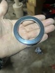
Ok, new bushing is into the assembly. One of the short case bolts ripped out its threads as I removed it, so I am going to tap and install a 12mm bolt then I can re-assemble the P6…

While I was looking thru as much of the assembly as I could access trying to fully understand it, I came to realize that the center clutch disc carrier cannot move as far forward as I initially measured, as the main front snap ring and compressed discs do not limit the forward travel of the center carrier, the center shaft does. I came to realize that if it did move as far as the snap ring and discs allow, with the center carrier pulled all the way forward with discs compressed against the snap ring, even the 8.5MM/.335” thrust bushing could still slide far enough forward to fall off of its perch on the center spindle.

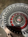
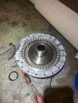
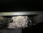
So I looked around a little more and went out and installed the clutch carrier onto the splined center shaft and pushed it all the way forward. At the front of the splines on the shaft there is a raised step. The long snout on the clutch carrier contacts this, stopping its forward travel before the curved/flaring base of the carrier snout contacts the bearing cover plate… in this full forward position, using a straight edge, I measured from the front face of the disc carrier to the gasket face where the p6 cover bolts on. It was right at .750”

I re-assembled the carrier and clutch discs back into the case resting on the new .335” thrust bushing. Using a straight edge I again measured the distance between the front of the disc carrier and the gasket face on the P6 housing… this worked out to be right at .800” in light of this revelation the bushing cannot come off its center carrier perch. And it appears that with the new bushing in place, the disc carrier has ~.050” of free travel. It also means that with the original ~3.5mm(.138”) roller thrust bearing, the carrier had ~.247” of free travel…

So what causes this roller bearing failure? Repeated tapping of clutch and carrier against roller bearing? Repeatedly accelerating the bearing from a standstill with each contact? or as 87CR250R indicated, only lightly loading the bearing? or perhaps all of the above… Looking at the configuration, it probably should have been a thrust bushing in the first place… the failures appear to be low and random, but they do fail…

has anyone heard or seen a failure with the second roller thrust bearing Allison specified?

Anyway, time to re-assemble.

FWIW…
 

Plasa

Well-known member
Steel Soldiers Supporter
270
334
63
Location
Italy
Just a stupid question. If it's a matter of spacing, why not keep the original bearing and add a washer to get the 8.5mm space? And the spacer can be of alluminium or plastic, easy to make and the bearing is always under load.
Christian
 

Ronmar

Well-known member
4,395
8,303
113
Location
Port angeles wa
Just a stupid question. If it's a matter of spacing, why not keep the original bearing and add a washer to get the 8.5mm space? And the spacer can be of alluminium or plastic, easy to make and the bearing is always under load.
Christian
Gauging the proper distance would be the tricky part as the shaft it rides on will expand and contract with temp changes(changes shaft length) and changing your amount of bearing load….

That space is also where ALL the lube oil that feeds the clutches, keeping them “wet” comes from, so there needs to be a few thousandth of clearance across the face of the bearing to allow oil to pass, which would keep you from being able to load the bearing…
 

Ronmar

Well-known member
4,395
8,303
113
Location
Port angeles wa
Here are some pics to show oil flow. In the first pic the pressurized oil is delivered to the center rear of the P6 housing to that hole in the middle it flows up and around the end of the shaft following the red line, between the shaft and its rear plain bearing, then forward along the center hole to the lip where it spreads outward over the front face of the thrust bushing/roller bearing(just inside the ends of the splines seen in this pic). Remember the center shaft and everything forward of the thrust bushing is spinning unless the P6 clutch is engaged.


IMG_4162.jpeg


As the oil flows into the area of the thrust bushing, all around the shaft in the first pic it must flow outward between the new thrust washer/bushing(or the old roller thrust bearing) and the rear race of the clutch disc carrier seen in this second pic(green circle is the race, red arrow is the oil path. The oil has to be able to get past the disc carrier race and the thrust bearing. Since this is usually spinning, the oil if flung out radially into the channel formed by the raised rear lip(yellow) Of the disc carrier. The centrifugal force causes the oil to exit this channel thru the staggered holes and spread out into the clutch pack to keep the spinning and stationary discs wet and spinning freely when not commanded to lock together by the P6 piston/1st gear command…

I do not know how much lube pressure reaches this location and I suppose a little may pass up along the splines but they are a pretty tight fit. At any rate any pressure built up will act hydraulically upon the disc carrier as it does upon the center shaft. The center shaft is 1.4” in dia so has ~1.57 sq in of surface area at the back, so every 10PSI of oil coming in thru that center hole = 15# of forward thrust on the center shaft… That rear bearing face of the center disc carrier if you include the rear ends of the splines is a little over 4 sq/in of surface area. You put 10PSI there and you get 40# of hydraulic force pushing forward on the disc carrier until oil can pass outward to reach the holes…

I really don’t see the need for a roller thrust here, it probably should have always been a thrust washer…

IMG_4163.jpeg
 
Last edited:

Lifeson

New member
20
12
3
Location
italy
Ciao Ronmar, ho seguito attentamente tutta la tua descrizione. Ho notato che il cuscinetto reggispinta ha una scanalatura sulla superficie superiore; sai se ne ha una anche sulla superficie inferiore o piatta?
PS: Ho già sostituito il cuscinetto con uno nuovo perché, cambiando l'olio, ho trovato dei piccoli cilindri sul magnete del tappo. Finora tutto sembra funzionare correttamente, ma non ho fatto molto.
 
Top