• Steel Soldiers now has a few new forums, read more about it at: New Munitions Forums!

  • Microsoft MSN, Live, Hotmail, Outlook email users may not be receiving emails. We are working to resolve this issue. Please add support@steelsoldiers.com to your trusted contacts.

MP-803A - Will not Crank from S-1

Maestro

New member
12
4
3
Location
Doylestown, PA
Hello everyone,

First, I want to thank everyone here for this resource, I probably would not have bought this generator without having this knowledge base available. I never worked on a diesel motor so this part is new to me. I have a gas generator and work on gas engines all the time. Building a home in the country side which is prone to power outages during bad storms and can it take days and weeks to get powered restored. The plans it to use the MEP-803a as the whole house generator.


I hope someone can point me in the right directions. I recently bought a 2010 MEP-803a with 280hrs from GovPlanet, it was in great condition. Got it home last week and found it was completely mothballed, they pulled all the fluids, filters and batteries. Not sure if while draining fluids they broke the fittings off the main fuel pump or this was the reason it was put out to pasture. It could not be repaired, as everyone knows those original pumps can not be sourced anymore. I located a universal replacement 24v pump and got it working. I installed all new filters, loaded the generator up with all the necessary fluids and new batteries and tried to get it started.

The engine will turn over using the dead crank switch (S-10). When S-10 is in normal position and S-1 in Prime the pump will cycle for a period of time and stop. I verified the fuel made its way to all the necessary places. The first couple of time I tried starting from S-1 all I got was a click, like a large contractor closing almost like a starter solenoid, but it did not engage the starter. I also notice the low oil pressure light came on after turning S-1 back to the prime position and it would not do anything until I manually cleared the indicator. After doing this a couple times I decide to use the S-10 to crank over the engine for about 10 or 20 second after doing this a couple of time. The low oil pressure light stop coming on after turning S-1 to the start position, but I still get click sound and the starter does not engage. I looked at the relays, not sure of the designator since there are no labels, I can see the third relay from the left is activating when S-1 is turned to the start position.

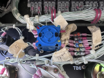
The generator has been worked on in the past, the water pump has been repaired, all kind of RTV was used to seal it back up. S-1 was replaced at one point, see attached picture, someone labeled all the wires to make sure they returned to the correct locations. As best I can tell, they are correct, but I plan to verify the wire numbers against the useful chart that was share here. Also when I open the control panel for the first time, all the metal clips holding the relays in place were off. Not sure if they vibrated off or they were removed. I pulled all the relays and reinstalled them and replaced the retaining clip (not a great design). I also check J-7 and J-6 and those connectors were clean and could not see any corrosion as some people have reported. I was concern about this since this unit was came from Nation Guard Station in Alabama.

I hope I gave someone enough information to help me figure out what it the culprit here or where to look. I know the generator set has a number of fail safes and I am wondering if one of those is causing the problem.

TIA!!!!
 

Attachments

Maestro

New member
12
4
3
Location
Doylestown, PA
I decided to open everything up to see if any wires were disconnected or broken since it was obvious the top lids were removed. Found mouse nest but all wires where they are supposed to be. Did figure out where contactor sounds was coming from, it was relay K18, pre-heater, the other relay with is activated in the start position of S-1 is K-15 field flash relay.

At this point I’m not seeing anything obvious, I did check the voltage at starter solenoid, using the dead crank switch I was expecting to see 24v at terminals, only saw volt meter bounce around and settle back zero. This makes no sense since engine turns over.

Could S-1 be bad? What should I check to know.
 

peapvp

Well-known member
Steel Soldiers Supporter
1,290
1,644
113
Location
Basehor, KS
I decided to open everything up to see if any wires were disconnected or broken since it was obvious the top lids were removed. Found mouse nest but all wires where they are supposed to be. Did figure out where contactor sounds was coming from, it was relay K18, pre-heater, the other relay with is activated in the start position of S-1 is K-15 field flash relay.

At this point I’m not seeing anything obvious, I did check the voltage at starter solenoid, using the dead crank switch I was expecting to see 24v at terminals, only saw volt meter bounce around and settle back zero. This makes no sense since engine turns over.

Could S-1 be bad? What should I check to know.
I would start with TB6
It is apparent that someone has taken wires off this terminal block and put them back on haphazardly.
There is a good chance that the wires were not connected to the correct terminal position
IMG_4606.jpeg

the wiring diagrams are in the -20 TM’s and I am having issues zooming in in the pdf’s on my iPhone 18.6.2 iOS

TM’s
 

peapvp

Well-known member
Steel Soldiers Supporter
1,290
1,644
113
Location
Basehor, KS
And @Maestro looking at your picture of TB6, there is most likely the metal bridge between Column 1 and 2 missing which connects these two columns and ties everything to ground. At least I am not seeing the metal bridge.
 

2Pbfeet

Well-known member
735
1,464
93
Location
Mt. Hamilton, CA
And @Maestro looking at your picture of TB6, there is most likely the metal bridge between Column 1 and 2 missing which connects these two columns and ties everything to ground. At least I am not seeing the metal bridge.
Nice catch! Counting connections, and not seeing the bridge, sure makes it seem as if the connection to ground is missing for #2.

That sort of oversight always makes me nervous about what else is missing.

@Maestro this is a typical bridge or jumper;
1756749549285.png

All the best, 2PbFeet
 

Maestro

New member
12
4
3
Location
Doylestown, PA
Thank you guys. I just verified that all the wires were correct, and was not making sense to me. Just started tracing back from starter to see where the contraction was broken, I figuring it was one relays that was problem. I did not find that schematic, I hate the way they have the drawing organized.

I’m out for afternoon, when I get home I’ll give that try.

thanks again!!!!
 

Maestro

New member
12
4
3
Location
Doylestown, PA
Looking at the schematic for S-1 it looks like all the positive terminal 2, 4, 6, & 8 should be tied together, is this done internal to the switch or does it require external jumpers. I started looking at the other TB to make sure their jumpers were in place, they all look to be correct.

Screenshot 2025-09-01 at 6.06.35 PM.jpg
 

peapvp

Well-known member
Steel Soldiers Supporter
1,290
1,644
113
Location
Basehor, KS
Okay, put in a jumper, it did not fix crank issue, but fix one of panel lights which I thought was burned out, the jumper ties all lights grounds together.
That’s good that you fixed this issue even though it did not remedy your start issue.
Besides of this connection being the ground for three lights, it is also the ground for M3, the time meter and TB5-8
TB5 - 7, 8, 9 and 10 tie all grounds together with TB6-1, 2 which is the common ground for the control panel.
This would have caused you a lot of grief after getting the Genset to start.

Besides this, the missing jumpers are extremely difficult to troubleshoot.
One has to to breathe, defalcate and eat these gensets in order to mastering this problem
 
Last edited by a moderator:

Maestro

New member
12
4
3
Location
Doylestown, PA
Can someone point where "T" connection in the below schematic is coming from. Based on the fact S10-1 Dead Crank works tell me the connection (wire 114C) from S10 to K2 (crank relay) is working, K2 is energizing and providing L4 (starter Solenoid) with power. I have not found the location of K2, can someone point in the right directions. This also tell me K16 to L5-Pull to C to ground must be working at well. Can someone tell me what L5 is and where it is located.

The only other way K2 will get energize is from the "T" connection between S10-1 and K2-X1. I want to trace that back to see if it getting power.


Screenshot 2025-09-01 at 8.36.10 PM.jpg
 
Last edited:

peapvp

Well-known member
Steel Soldiers Supporter
1,290
1,644
113
Location
Basehor, KS
Can someone point where "T" connection in the below schematic is coming from. Based on the fact S10-1 Dead Crank works tell me the connection (wire 114C) from S10 to K2 (crank relay) is working, K2 is energizing and providing L4 (starter Solenoid) with power. I have not found the location of K2, can someone point in the right directions. This also tell me K16 to L5-Pull to C to ground must be working at well. Can someone tell me what L5 is and where it is located.

The only way K2 will get energize is from the "T" connection between S10-1 and K2-X1. I want to trace that back to see if it getting power.


View attachment 953281


if you want to check K2, remove the top of the control panel. k2 is behind the bulkhead. Simple way to check it is this. Remove the plastic cap on K2, so you can see the contacts.
 

Guyfang

Moderator
Staff member
Moderator
18,041
27,048
113
Location
Burgkunstadt, Germany
With S1 in the run position, S1-2,4,6,8 should all have 24VDC. Do you have 24VDC at all those places?

If so, place the S1 in the start position and hold it there. Do you have 24VDC at S1-1, S1-7, S1-3 and S1-5?

The switch could be bad. They are not world renown for reliability. You are testing all over the place, and need to start at the S1 and follow the power to the K2. You know the K2 is good if the set turns over with the S10.
 

Maestro

New member
12
4
3
Location
Doylestown, PA
I finally had some time to get back to debugging the electrical issue.

I have verified all the correct voltages are on S1, depending on position of switch. I have 24V on S1 - 2,4,6,8 when S1 is in the start position I get 20V on pin 7, I followed that to K12 (Engine Fault Relay) pin 8 to pin 2 (N/C) should have 20V, and this is where the first problem appears. When I go through the start sequence the first time, from off to prime to start I get 19V at pin 2 to but no start, as soon as I release I get the oil pressure error light and K12 is energized and no power at pin 2. I clear the error, but it does not de-energize K12. I have to put the S1 back in off position and start over again.

K12 get power on Pin A which comes from S7-pin 7 as well as Pin 4 of K12 which is normally open until K12 is powered. Obviously the power is not coming from S7-7 so it coming from K12-4 which creates a lockout condition thus the reason you have to remove all power to reset. Pin 4 is connected to Pin 7 which is connected to S14-7 (crank disconnect switch), K19 (fuel level relay) pin A ( Power for relay)

In order for power to get to the starter L4, the power signal also goes through K16 (Crank Disconnect Relay) and K2 (Crank Rely) I know K2 works since S10 Dead Crank works. Looking at K16 the only way the signal gets through, it has to be energize when switch S1 is turned to start, this relay does not energize until after the S1 is released. Which means the power to A and B pins on K16 are not getting power at the right time. Pin B (ground) is connect to S14-1 and Pin A (positive) is connected to K20-4 K20-9 (oil pressure relay), and K12-1 so any of those relays can provide 24V.

I am at the point where can someone tell me how do you check S14 that it is working properly. I looked at it and do not see any obvious failures. Since the fuel level relay is in the circuit, how much diesel must be in the tank, I only put in a couple of gallons, did not want to fill it until I new it was running. The other possible fault is oil pressure, I put enough oil in it and check it a couple of time and it all the way up on the dip stick. As said before if I dead crank it for a little be before trying to start it do not always get the oil pressure fault light. Lastly, and you might have noticed the voltages, going through S1 the voltage drops from 24 to 20V and as the signal goes through the relays it drops to 19volts. This definitely is not normal. not sure of the drop in S1 it could be due to the diode across pin 7 to pin 1. can someone verify what is correct.

Just an FYI, I put a starter button on the L4, while holding S1 in the start position I pressed the stater button and the engine turned over but did not start. this tell me something is disabling the starting.

Any insight where to look next.
 
Top
AdBlock Detected

We get it, advertisements are annoying!

Sure, ad-blocking software does a great job at blocking ads, but it also blocks useful features of our website like our supporting vendors. Their ads help keep Steel Soldiers going. Please consider disabling your ad blockers for the site. Thanks!

I've Disabled AdBlock
No Thanks