• Steel Soldiers now has a few new forums, read more about it at: New Munitions Forums!

  • Microsoft MSN, Live, Hotmail, Outlook email users may not be receiving emails. We are working to resolve this issue. Please add support@steelsoldiers.com to your trusted contacts.

11:00 R x 20's on deuce/135 rims

FSBruva

New member
629
1
0
Location
Marietta, GA
Are we confusing offset to mean two different things? Sounds like Tony is describing the distance to the center of the rim, and gerhard is decribing the distance to the other side of the rim?

Maybe.

Matt
 

houdel

Active member
1,563
8
36
Location
Chase, MI
Thanks again Ken. Now one final question - When installing a single wheel on the now flipped hub, do you secure it with the studs, or do you install the studs first, then the wheel and secure with the nuts, or doesn't it make a difference? Given a choice, I'd rather go studs, wheel and nuts for aesthetics and ease of installing the wheel.
 

cranetruck

Moderator
Super Moderator
Steel Soldiers Supporter
10,350
75
48
Location
Meadows of Dan, Virginia
Lee, I'm probably missing the point of your question, but the rear wheels are now installed just like you install the front ones, on the studs.
This is what I do (image), this way I have a "step" when getting up on the bed from the sides.
 

Attachments

Recovry4x4

LLM/Member 785
Super Moderator
Steel Soldiers Supporter
34,014
1,814
113
Location
GA Mountains
Perhaps we forgot to mention that when the hubs are off, you remove the studs and reinstall them facing the opposite direction. This affords wheel installation just as normal. Trust me Lee, when you tear into this, all the foggy areas will become crystal clear.
 

houdel

Active member
1,563
8
36
Location
Chase, MI
One picture is worth 10,000 words, Bjorn's photo answered my question. What I was asking was if the single wheel on a flipped hub was installed like an inner dual (wheel over hub studs, secured with an inner dual stud) or like an outer dual (wheel over inner dual stud, secured with a lug nut). Bjorn's photo clearly shows the inner dual studs installed before the wheel, then the wheel, then the lug nuts (although Bjorn is a little stingy with the lug nuts). That is precisely what I wanted to know. Thanks again.
 

patch

Member
154
1
18
Location
Buxton Maine
Lee, you want to look carefully at the photo. What Bjorn has done is use the inner dual studs(we called these 'caps' when I was a motor pool monkey) as lug nuts to provide a step point to reach the truck bed. Half the lug nuts on each wheel are caps, half are regular front wheel lug nuts, so the tire is in fact secured with the proper number of nuts.
 

Tony

New member
141
1
0
Location
Camarillo, Calif 93012
FSBruva, you are correct.. The dimensions that I put in here I got from the manual..and offset is from the cl to the outside of the rim..this is a critical dim if you cange wheels with a greater offset..because it will put a greater load on one side of the bearing (lateral load) which would ruin your bearings
 

houdel

Active member
1,563
8
36
Location
Chase, MI
Ken - Got it. I've never seen that done before, when I go back to Bjorn's photo I can see the "caps" as you call them protruding out further than the studs where the nuts are. Thanks for the clarification!
 

gringeltaube

Staff Member
Super Moderator
Moderator
Steel Soldiers Supporter
6,888
2,274
113
Location
Montevideo/Uruguay
Tony, Matt and others: just to make sure we're speaking the same language and not confusing anything, this is a std. M35 wheel, (cut), showing the real (exact) dimensions in proportion and how the offset is measured.

I know, we are a little off topic now, but since everybody now is talking about M135 wheels I would like to confirm the measurements of all other deuce wheels as well, may be do some additional drawing for a technical article?

Gerhard
 

Attachments

Loose Deuce

New member
470
0
0
Location
South MS.
Well that's how I thought off set would be measured but I dont have a m135 wheel to measure. The pictures on this thread shows about 9½" off set compared to the m35 10½" off set. Hell one inch difference, how can that be worth the effort and expense ?

I dont think one inch can be that bad on the bearrings as far as extra load on the outer bearrings, Thought these things were over engineered. With the hubs flipped would that make the difference ? Have I over looked something? :?
 

gringeltaube

Staff Member
Super Moderator
Moderator
Steel Soldiers Supporter
6,888
2,274
113
Location
Montevideo/Uruguay
The drawing below shows the relative position of an M34/M135 single wheel/tire on a reversed hub vs. the M35 duals. It's exactly centered to the duals.
I would say that strain on bearings due to twice the weight and extra leverage while running over obstacles is actually worse with duals!

And I'm sure that the rear spring center pivot bearings also will benefit from running singles. Certainly one "thing" that was NOT over-engineered in the deuces!

Gerhard
 

Attachments

czechsix

Member
90
2
8
Location
Meadow Lakes, Alaska
Good thread...those Michelin XL 11.00x20's are exactly the same ones that I'm going to run as duals on my truck. The fronts go on sometime this week...still have to get some more for the rears.
 

G744

Well-known member
Steel Soldiers Supporter
1,593
3,493
113
Location
Hidden Valley, Az
A M135 is a 1950's GMC duece (gasser 302 & 8-speed Hydramatic) with singles all around factory. Has a narrower bed so it looks and rides OK with them.

The same wheels were also used on the M34 Reo duece (alongf ith the narrow bed) and the M104 1.5 ton trailer.

BTW, all duece wheels for the M-series trucks can run up to a 12.00-20 as intended by both Firestone and Goodyear, the makers of the LTS wheels.

dg
 

Tony

New member
141
1
0
Location
Camarillo, Calif 93012
Basic info on wheel offset - Gerhard your diagrams are quite interesting, but what you have defined as "offset" is not "offset and offset is not the rear spacing.
Offset is defined as " the offset of a wheel is the distance of the hub moumting surface to the centerline of the tire mounting. " This definition is defined by SAE.. if you are interested in how to measure wheel offset the following site will give you that info..I think I have it right , from memory < www.rsracing.com/tech/wheel.html >

Enough said about off set, the numbers I quoted previously is from the M-135/M-211 spec manual.
 

gringeltaube

Staff Member
Super Moderator
Moderator
Steel Soldiers Supporter
6,888
2,274
113
Location
Montevideo/Uruguay
Thanks Tony, you are right. I have to admit it: I have been using the terms backspace and offset like everybody else in our country, as if they where synonyms and just confirmed they are not! :eek:

Offset = Backspace - (Rim Width ÷ 2)

According to your specs, backspace of an M135 wheel would be 9 ¼”.
Could you please confirm this by measuring it next time you take a wheel off?
I’ve found 9 ½” for M34 wheels and now I wonder if there is any difference in design between both?

This is the corrected drawing of my previous post:
 

Attachments

Tony

New member
141
1
0
Location
Camarillo, Calif 93012
gringeltaube,

I measured the dim you asked me to, the tire is on the wheel so it is a little difficult to handle...but the dim I got is 9 -7/16" thids is compared to the 10 1/2 dim on your last sketch,,,now the dim I gave you could be a little off, just put a flat bar on the rim and measured , but it should be close enough to tell you what you are looking for.

Tony
 

gringeltaube

Staff Member
Super Moderator
Moderator
Steel Soldiers Supporter
6,888
2,274
113
Location
Montevideo/Uruguay
OK, thanks a lot. 9 7/16” is very close to 9 ½”, so this would confirm that backspace of M135 wheels is almost the same, if not identical to M34 wheels. This also means that equipped with these wheels the std. M35 (front-) track width is increased by just two inches. Hard to believe that this alone will ruin your bearings.

Gerhard
 

Tony

New member
141
1
0
Location
Camarillo, Calif 93012
Gerhard,
just think of the bearing being a single load bearing span and the contact point ( where the load is bearing on the span) is equally distributed across the entire span. Now instead of the load being concentrated equally on a 3" span ( approx bearing width) it is now shifted to the outer end of the bearing which would receive most of the load..
Example; if the load on the front wheel is 600# then the 600 # load would be equally transmitted to the three inch span...( which would be within design limits). Now if you shift the load to the outside by 2", then the load is being distributed more on the outer 1" or less of the bearing, which could overstress the bearing and cause a failure.( being over the design limits)
Hope you understand what I'm trying to say with drawing a load force diagram.
 

cranetruck

Moderator
Super Moderator
Steel Soldiers Supporter
10,350
75
48
Location
Meadows of Dan, Virginia
Guess next question is, what is the design load of the bearings?

You are right on with the increase in track width, it's about 3-3/4 total for the singles config. The 1100's are wider too, so that also comes into play, especially when aired down.
 

houdel

Active member
1,563
8
36
Location
Chase, MI
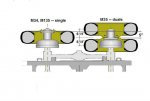
Guys, I think you are making mountains out of ant hills. First off, the load is not uniformly distributed across a uniform span, it is concentrated at the edges of the span, i.e., the bearings. As long as the wheel offset (C/L of wheel) is somewheres between the bearings each bearing will still see a vertical up load, if the wheel is perfectly centered each bearing will THEORETICALLY see an equal load; if the wheel is offset somewhat one bearing will have a slightly higher load than the other.

That is on a straight, level road. What about curves and turns? Now, in addition to the vertical load imposed by the weight of the vehicle, the wheel is applying torque to the bearing set due to the side thrust of the wheel. On a hard right turn, for example, the left inner bearing is seeing a vertical up load at least equal to the total dead weight on the wheel PLUS the dynamic load caused by the torque created by the side thrust forces imposed on the wheel in turning the vehicle; the left outer will see a vertical down force from the turning torque. The bearing loads on the right bearing set will be nearly the same but reversed. Frankly, I doubt the bearings give a damn whether they are loaded up or down, as long as the contact force of each roller to the race remains within design limits the bearings will just keep rolling along.

And what about the rear duals? Between mismatched tires, crowned roads and uneven road surfaces the rear bearings are CONSTANTLY being torqued and that torque is CONSTANTLY varying in direction, and assuming the truck is heavily loaded, the total bearing loading is probably in excess of the total front bearing loading.

Remember also that the front and rear AND inner and outer bearings are the SAME bearing, inner bearings have a slightly larger ID but the rollers, races and cages are the same so the bearings are all designed to the same load limits. This is a very different situation, for example, of the front wheel bearings of a rear wheel drive vehicle; here the inner bearing is quite large and the outer bearing much smaller. In this case wheel offset is critical to avoid overloading the smaller outer bearing.

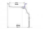
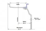
My point? As long as the offset of the wheel places the centerline of the tire somewhere near the center of the bearing, an inch or two one way or the other makes no significant difference!
 
Top
AdBlock Detected

We get it, advertisements are annoying!

Sure, ad-blocking software does a great job at blocking ads, but it also blocks useful features of our website like our supporting vendors. Their ads help keep Steel Soldiers going. Please consider disabling your ad blockers for the site. Thanks!

I've Disabled AdBlock
No Thanks