• Steel Soldiers now has a few new forums, read more about it at: New Munitions Forums!

  • Microsoft MSN, Live, Hotmail, Outlook email users may not be receiving emails. We are working to resolve this issue. Please add support@steelsoldiers.com to your trusted contacts.


15K Diesel Gen set

2deuce

Well-known member
1,429
104
63
Location
portland, oregon
Its built by Stewart-Stevenson on a trailer. It says 15K CTMGSA or CMTGSA. I don't have a manual and am trying to figure out what I have here. It says 208V 3PH with a plug in for 120V. 60Hertz. I need an education if someone can help. Thanks
 

Recovry4x4

LLM/Member 785
Super Moderator
Steel Soldiers Supporter
34,014
1,813
113
Location
GA Mountains
NSN; 6115-01-304-8184

Parts TM #; TM 9-6115-655-24P
Can't tell ya much else from this end.
 
Last edited by a moderator:

OPCOM

Moderator
Steel Soldiers Supporter
3,657
26
48
Location
Dallas, Texas
according to this, the set makes 120V to neutral, so it is a WYE setup.

If you need 120/240V, and if indeed the alternator is a 6 (or 12)-wire one, and all three (or 6) windings have both ends available for connecting, you can convert that to a single phase 120/240VAC set by placing two of the phases in series. They will geometrically (phase vector) add to make 120V, which will be 180 degrees out of phase with the remiaining 120v winding. The power available with this setup is about 67%-75% of the full power.

Otherwise you can just put three separate 120V 5000 watt 'outlets' on it. that is, each phase = 120V at about 40 amps.
 

Attachments

OPCOM

Moderator
Steel Soldiers Supporter
3,657
26
48
Location
Dallas, Texas
The short answer is that these have a switch to do that for you.

The MEP-016 and MEP-017 are 6-wire 3-winding sets. I'll be the first to admit I do not know those sets, nor the one mentioned above, personally.

I only know that to rewire a 208V WYE for single phase 240/120V, the connections are re-done as shown. This is what I did on my 40KW Mankato set at home, according to the manual. Additionally, the voltage may still be 208V/104V instead of 240V/120V unless the regulator is adjusted afterwards. It depends on how the regulator is connected to sense its voltage. It is usually not a big deal to set right.

See TM 5-6115-332-14 and TM 5-6115-271-14 and comments below.

The MEP-016A is the 3KW 60Hz unit equipped with a selector switch to set it for single phase or three phase, and various voltages including 240/120V single phase.

The MEP-017A is the 5KW 60Hz unit equipped with a selector switch to set it for single phase or three phase, and various voltages including 240/120V single phase.

The MEP-021A is the 3KW 400Hz unit equipped with a selector switch to set it for single phase or three phase, and various voltages including 240/120V single phase.

The MEP-022A is the 5KW 400Hz unit equipped with a selector switch to set it for single phase or three phase, and various voltages including 240/120V single phase.

The MEP-026A is the 3KW 24VDC unit. (great for charging the olde deuce or running a couple GRC-106's!)
 

mangus580

New member
6,010
282
0
Location
Western NY
Yeah, they make single phase, but not in the 'normal' sense. When you set the switch to 240 single phase, you have 240 volts to ground/neutral on ONE wire... If that makes sense...
 

2deuce

Well-known member
1,429
104
63
Location
portland, oregon
Thanks for the input. My electrical knowledge is very limited. It says on the machine that the voltage between phases must be kept within 10%. There is a selector switch that I believe reads the voltage between the lines. There is a junction box L1,L2,L3,L4, no plug-in for the 208 volts. There is one 120volt regular recepticle plug-in. Is 208 volts an oddity or a generator voltage? Is it compatible with 240 3 phase? I thought I would use this generator to power my shop which has no power yet. Is anyone out there using this generator? It is Deutz aircooled diesel powered. I'm going to call Stewart-Stevenson to see if a manual is available. Thanks for the help. Greg
 

OPCOM

Moderator
Steel Soldiers Supporter
3,657
26
48
Location
Dallas, Texas
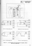
Ok I see the point. They do not make single phase 120V and 240V at the same time. In that case, the above reconnection diagram could apply. The AC gensets I mentioned all show to be three-coil, six-wire sets. Trying to study the manuals from a standpoint of changing a wire or two and having 120+240V single phase, the MEP-016 manual figure 6-3, figure 8-1B, and best of all figure 8-3 seem to show a large terminal strip with 6 junctions. These are possibly the '6 wires' which should disappear into the alternator itself. Figure 10-1 is a pretty good diagram, showing the voltage selector switch contacts labeled "S1" and tagged with various terminal numbers. Unlike a conventional electronics diagram, the switch is represented in the electrician's manner so it is not clear at first what connections are made in any specific mode. diagram FO-1 also shows the switch S1 and what wires go to it, but not the important part which is the insides of the switch. That's the missing information. From fig. 10-1 would be the place to start any divinations.

For the 5K set, MEP-017, table 7-1 shows the connections for its switch S1. This in conjunction with diagram FO-1 might clear things up as to the switching and any rewiring to be attempted. Diagram FO-2 is probably the most useful for divining.

In either case, it is entirely conceivable that adding another switch or perhaps simply a wire could allow the set to be placed in the 240V position and derive two 120V supplies to emulate house current. I'll draw some pictures on the diagrams, might be too big to post here due to 640x480 restriction.
 

OPCOM

Moderator
Steel Soldiers Supporter
3,657
26
48
Location
Dallas, Texas
attachment is the zipfiles of schematics showing switching and current flow highlighted for each mode of the MEP-017 and the file 240V_1phase.gif shows where to check for a "neutral" when the set is set to 240V single phase. I suggest the neutral is the T5-T6 conection. I suggest the MEP-016 can be done the same way. Keep in mind the total power output is less than the rated output with this connection. I did not find a ground in the schematic connected to any pole in this mode, so it should not be 240V to GND, unless you ground a terminal yourself. In such a case, the neutral would be the one to ground.
 

Attachments

OPCOM

Moderator
Steel Soldiers Supporter
3,657
26
48
Location
Dallas, Texas
2deuce said:
Its built by Stewart-Stevenson on a trailer. It says 15K CTMGSA or CMTGSA. I don't have a manual and am trying to figure out what I have here. It says 208V 3PH with a plug in for 120V. 60Hertz. I need an education if someone can help. Thanks
I did not mean to hijack the thread, did you have time to check the alternator for the number of wires coming from the stator?

also similar model?
CMGT-Quiet generator-Deutz 5KW,15KW,30KW
http://www.stewartandstevenson.com/Services/Products/GovernmentSales/Product+Support.htm
 

OPCOM

Moderator
Steel Soldiers Supporter
3,657
26
48
Location
Dallas, Texas
RE: Re: 15K Diesel Gen set

If I had an MEP-xxx set to play with, I would be glad to figure out and document the means of making 120/240v 3-wire single phase from it. But I think there's enough here. Also, according to the Stewart-Stevenson nameplate data indicating it has a 120V outlet and produces 208V 3 phase, there is a very high confidence it can be easily converted to 120/240v 3-wire single phase. How many amps is the 120V outlet rated for (breaker size)?
 

OPCOM

Moderator
Steel Soldiers Supporter
3,657
26
48
Location
Dallas, Texas
I believe there are two errors in the "240 VOLT 1 PHASE CONNECTION" diagram in the MEP-016B manual (TM 5-6115-615-12).

1. Two T-2's are shown. The terminals should probably read, from left to right:
T-1 T-4 T-2 T-5 T-6 T-3
.. although any arrangement of the coils which gives the same polarity arrangement could also be correct:
+ - + - - +

coils:
T1-T4
T2-T5
T3-T6

2. The voltage shown says "120V", but it is supposed to be "240V"

Since the diagrams may be confusing, and a goal is to get 120/240V, then the use of a single winding for one side of the 120V is not in need of explanation. The use of two identical windings in series to get the other 120V, that is the other side of the 240V and have it be 180 degrees out of phase is in need of explanation. It has to do with the polarity of the windings. If the two windings are connected so that they apparently oppose each other, the output of these seriesed pair of windings is 208V. If they are connected so as to apparently aid one another, the output is 120V. The polarity of this seriesed set of windings determines its overall phase relationship to that of the single winding. Think of T1, T2, T3 as the "+" end and T-4, T-5, T-6 as the "-" end of the windings.
 

Attachments

2deuce

Well-known member
1,429
104
63
Location
portland, oregon
I went out to try an tell how many wires come out of the alternator but its not easily accessed and I can't see any wires at all. Its very enclosed with all the sound deadening insulation. The breaker on it isn't labeled so without a manual I don't know how many amps. Its a Leroy-Somer 15K alternator that runs at 1800rpm. I didn't see it in their family of alternators they make now from their website, but if there is any info on the data plate that would be helpful...
 

BillP

New member
1
0
0
Re: RE: 15K Diesel Gen set

Thank you very much, OPCOM! An amazingly complete explanation with color schematics even. I verified split phase from my MEP-017 using L2, L3 and the "hot" terminal of J3 for the neutral.
 
Top
AdBlock Detected

We get it, advertisements are annoying!

Sure, ad-blocking software does a great job at blocking ads, but it also blocks useful features of our website like our supporting vendors. Their ads help keep Steel Soldiers going. Please consider disabling your ad blockers for the site. Thanks!

I've Disabled AdBlock
No Thanks