• Steel Soldiers now has a few new forums, read more about it at: New Munitions Forums!

  • Microsoft MSN, Live, Hotmail, Outlook email users may not be receiving emails. We are working to resolve this issue. Please add support@steelsoldiers.com to your trusted contacts.


1984 m1008 cucv does not start

Minister956

New member
16
0
0
Location
Florida
Done that.


19. ENGINE CRANKS BUT WILL NOT START; ENGINE COLD; “WAIT” LIGHT OPERATES

Step 1. Ensure that key is in “OFF” position. Check for voltage between glow plug relay

terminal where orange lead connects and ground.

If there
IS voltage, replace glow plug relay (see paragraph 4-8) and perform

step 3.

If there is no voltage, perform step 3.

2-64

MALFUNCTlON


TEST OR INSPECTlON


CORRECTIVE ACTlON


CAUTION


DO NOT leave key in “RUN” position for more than 2 minutes. Failure to


follow this caution may result in damage to glow plugs.


Step 2. Turn key to “RUN” position. Check for voltage between glow plug relay terminal


where orange lead connects and ground.


NOTE


Glow plugs will cycle to 0 volts in approximately 20 seconds after first


operation. Time will shorten as glow plugs become hotter.


If there are 10.0-15.0 volts, ensure that engine is mechanically sound and fuel


system is operating properly,


If there are 22.0-28.0 volts, perform step 3.


If there is no voltage, perform step 4.


Step 3. Disconnect each glow plug lead and check for resistance between glow plug terminal


and ground. Resistance should be 1-3 ohms. Check glow plugs for looseness or


damage.


If any glow plug does not have correct resistance or is damaged, replace, (See


paragraph 3-20) Tighten any loose glow plugs.


Step 4. Tag and disconnect all glow plug leads from glow plugs. Check for voltage between


glow plug relay terminal where red lead connects and ground.


If voltage is 10.0-15.0 volts, connect glow plug leads and start engine.


If voltage is 22,0-28.0 volts, perform step 5.


If there is no voltage, trace circuit back to positive terminal board. (See wiring


diagram F-7 or F-8)


Change


Minister956

New member
16
0
0
Location
Florida
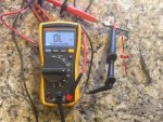
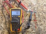
Okay, the multimeter was jumping from .2 and .3 ohms, unfortunately my fluke doesn't read hundredths.


Resistor may be hot. Use care when performing this step or injury to

personnel may occur.

Step 5.

Step 6.

Step 7.

Step 8.

Disconnect batteries, pull out bracket and resistor assembly (see paragraph 4-44,

REMOVAL, step 4), disconnect output (red wire) from relay, disconnect input (blue

wire) from input to resistors. Connect positive lead of multimeter to blue wire;

connect negative lead to red wire. Check resistance between resistors and ground.

Resistance should be 0.28 ohms.

If resistance is not correct, replace resistor, connect glow plug leads and

perform step 6.

If resistance is correct, connect glow plug leads and perform step 6.

Check for voltage between glow plug relay terminal where pink/black lead connects

and ground.

If there is voltage, perform step 7.

If there is no voltage, trace circuit. (See wiring diagram F-7 or F-8)

Check for voltage between glow plug relay terminal where light blue lead connects

and ground.

If there is voltage, perform step 8.

If there is no voltage, replace glow plug relay. (See paragraph 4-8)

Check for voltage at light blue lead on glow plug module.

If there is no voltage, trace circuit (See wiring diagram F-7 or F-8)

If there is voltage, perform
Electrical Troubleshooting malfunction #15.

2-65.0/(
 

doghead

4 Star General /Moderator
Staff member
Super Moderator
Steel Soldiers Supporter
26,247
1,168
113
Location
NY
Have you measured each GP for ohms?
 

doghead

4 Star General /Moderator
Staff member
Super Moderator
Steel Soldiers Supporter
26,247
1,168
113
Location
NY
Do you recall the readings?
 

Minister956

New member
16
0
0
Location
Florida
I took the GP's out and they were wet with diesel, the reading on them were less than .1 ohm. They looked very good.

I just got back from Auto Zone, they tested my batteries. The front battery (NAPA Commercial) was no good. The battery near the firewall was (newer Napa Commercial) 79%.
 

doghead

4 Star General /Moderator
Staff member
Super Moderator
Steel Soldiers Supporter
26,247
1,168
113
Location
NY
They need to be 1-3 ohms. Less(as yours are) is not good.
 

doghead

4 Star General /Moderator
Staff member
Super Moderator
Steel Soldiers Supporter
26,247
1,168
113
Location
NY
This is from paragraph/step 19,

Step 3. Disconnect each glow plug lead and check for resistance between glow plug terminal

and ground. Resistance should be 1-3 ohms. Check glow plugs for looseness or

damage.

If any glow plug does not have correct resistance or is damaged, replace,
 

doghead

4 Star General /Moderator
Staff member
Super Moderator
Steel Soldiers Supporter
26,247
1,168
113
Location
NY
Did your GPs have the original 3/16 wide connectors still, or have they been changed to standard 1/4" wide female blade terminals?

Go get yourself a set of AC Delco AC60G glow plugs and new connectors(if you have original terminals still), and I bet your all set.

After that, we have a few modifications that I really recommend you make, to be more reliable.
 
Top
AdBlock Detected

We get it, advertisements are annoying!

Sure, ad-blocking software does a great job at blocking ads, but it also blocks useful features of our website like our supporting vendors. Their ads help keep Steel Soldiers going. Please consider disabling your ad blockers for the site. Thanks!

I've Disabled AdBlock
No Thanks