• Steel Soldiers now has a few new forums, read more about it at: New Munitions Forums!

  • Microsoft MSN, Live, Hotmail, Outlook email users may not be receiving emails. We are working to resolve this issue. Please add support@steelsoldiers.com to your trusted contacts.

303M HydraMatic rebuild

m1010plowboy

Well-known member
Steel Soldiers Supporter
3,988
2,977
83
Location
Edmonton, Canada
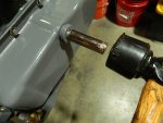
By George I might have this figured out. Is your close-up pic the inside of shaft Q (7411533) ?

That would mean shaft N (7084954) gets shoved inside shaft Q....and the infamous 'slop' occurs between the boy shaft N and the receiver hole in shaft Q.

Is that right?

P6150188.JPG


The description you posted from the TM 9-8025-2 the 301MG and 302M Hydra-matic transmissions manual helped a lot.

Were they sleeved from factory or is that something that happened when they went for maintenance the first time?
 

rustystud

Well-known member
9,400
3,376
113
Location
Woodinville, Washington
Thats the shaft. The bores are already bored out on all the 303M shafts I've seen so far. Though only two where actually to the proper size. The rest I had machined out to the correct size.
So it appears this is a factory problem and not a rebuild problem. Though if the mechanics who rebuilt these transmissions knew of this bushing they would have had them installed I'm sure. Since there is just that small paragraph and little diagram mentioned in "TM 9-825-2" I can see how they would miss it.
That passage the bushing fits into is a "main" pressure galley. All that pressure just "spurting" out around the input shaft would eventually cause severe wear since no pump could keep up with that kind of pressure lose for long. Also the wear on the pump itself. That would also explain the high failure rate of the front pumps on the 303M transmission.
 

rustystud

Well-known member
9,400
3,376
113
Location
Woodinville, Washington
I revised post #278 showing how to install the snap-ring holding the military shaft sealing unit on the shifter shaft.
002.JPGBasically you use a deep socket to "push" the snap-ring into it's groove. Using a rubber hammer give the socket a good "wack" and it will seat. With new "O"-rings it can be a real challenge to accomplish this task.
001.JPG
 

LItz

New member
1
1
3
Location
regina
Rusty,
With parts being so rare now have you any ideas about a more modern transmission and transfer case that could be used in the M135?
 

rustystud

Well-known member
9,400
3,376
113
Location
Woodinville, Washington
Rusty,
With parts being so rare now have you any ideas about a more modern transmission and transfer case that could be used in the M135?
Yes, I've thought about it a lot. There are several options I believe can work very well.
One being the "AT500" Allison. Note I didn't say the "AT1545" Allison which was used in the M35A3 Deuce.
That one has several problems with the torque converter. The tried and tested AT500 Allison has been used for decades and parts are plentiful. Put a good NP240 transfer case behind it (one that has been upgraded to the "Titan" shafts) and it will last you decades.
I believe I posted my rebuild of the NP240 here somewhere.
The other one is the "1000/2000" series Allison used in the newer Chevys. My 2019 Chevy 3500 has one.
I bought three core 1000's for $300.00 each. I'm actually tearing one down right now.
I already built a NP240 transfer case for this build. I plan on putting this behind my "MultiFuel" in my M35 A2 Deuce.
Now cost is a factor here. The older AT500 will cost around $500.00 in parts, plus the actual transmission.
The 1000 series will cost me around $5,000.00. Thats because I'm using the extremely strong "Input-mid-and output shafts" and also the HyPo C-2 clutch assembly along with the "Raybestos" clutch plates.
I'm also using a three clutch plate torque converter. And of course I will need a "stand-alone" control module. All that costs "bucko bucks" !
A good "stock" 1000 will cost around $1000.00 to rebuild and would work very well in a M135.
The biggest problem will be finding an engine adapter for the GMC 302 . Of course, if you're already going away from stock with the transmission why not just put in a crate 350 Chevy engine.
Now that combination of a 350cid engine along with a AT500 or 1000 series Allison would make the old M135 get up and "dance" !!!!
 

rustystud

Well-known member
9,400
3,376
113
Location
Woodinville, Washington
I have some new information I'm going to share today concerning the 303M HydraMatic's oil filter.
Almost everyone I've come across lately has shown evidence of wear. Some extremely bad.
So I went on a search to find a replacement. At first I asked if any filter manufacturer would make-up a few for our transmission. That did not go well. I don't believe anyone here would shell out a few hundred (make that $500.00) dollars for an oil filter. So I started looking at filters already made that could be adapted to our application. I found two that fit the bill.
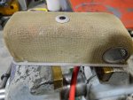
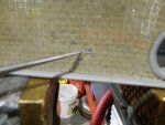
The first one has a smaller filter mesh. The standard HydraMatics filter has a #80 mesh screen made from brass weave. The filter I found has a #100 mesh screen (much better) and is made out of stainless steel. Also far superior to the easily damaged brass screen.
The second filter I found is an actual hydraulic filter capable of filtering down to 10 microns. It is also physically bigger so much more capacity. The problem is I'm not sure the oil pump will be able to pull the oil from it. I will need to test it to be sure it will work.
I assembled an oil pan to mock-up the filters.
Here's some pictures.

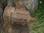
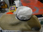
010.JPG009.JPG This standard brass filter has been around for over 60 years, and you can see the holes in the brass weave due to the brass becoming brittle.
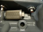
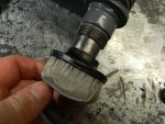
011.JPG This new filter is smaller but can still flow 10 GPM .
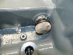
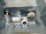
016.JPGFits perfectly on the end of the oil cooler.
012.JPG
017.JPG

018.JPGThis actual hydraulic filter also fits nicely into the oil pan sump. All it needs is a 90 degree elbow and a small piece of pipe. I've ordered the elbow ( reinforced silicone ) and some thin wall aluminum pipe which I'll thread to fit the filter. This set-up would be the best "if" the HydraMatics oil pump has enough suction to pull from it. Being forced to use old pump vanes gives me pause here.
I'm still looking into getting some new pump vanes made. I might have to go with the shop that wants
$275.00 for seven vanes and an order of 50 set's. We'll see.
Maybe I can sale some here or maybe "Fatsco" will buy the extras. Later on I'm going to build the last two 303M units I have parts for.
I'll probably put them on eBay. We'll see about that also.
 
Last edited:

rustystud

Well-known member
9,400
3,376
113
Location
Woodinville, Washington
Here's some "Tips" I'll share about building up the 303M's oil pan.
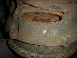
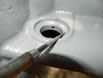
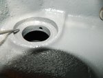
After cleaning up the pan you come across some holes in the oil cooler passage due to rust you can use some "High Heat Silicone" sealer to go under the sealing gasket. This silicone will fill the holes and set-up real nice preventing any oil and water mixing. We don't want the oil and water mixing.
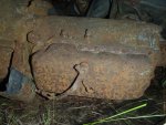
002.JPG003.JPGYou can see the divets the rust has made in the housing.
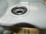
007.JPGPutting the silicone under the gasket will seal the holes preventing any leaks.
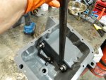
On another note.
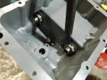
The TM calls for the oil cooler nuts to be torqued over 100 FT Ibs. That is almost impossible to do.
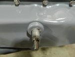
What I do is use a "Cheater Bar" on the end of my "spanner" wrench to give it that extra kick
I first tighten the nuts down until the seals are fully seated. Then I back the nuts off and apply some Loctite to the threads.
I use the "Red" Loctite to seal the nuts. The TM calls for "peening" the nuts. Very bad idea on a cooler that is no longer available. Use the Loctite instead.
013.JPG014.JPG
 
Top