• Steel Soldiers now has a few new forums, read more about it at: New Munitions Forums!

  • Microsoft MSN, Live, Hotmail, Outlook email users may not be receiving emails. We are working to resolve this issue. Please add support@steelsoldiers.com to your trusted contacts.


60 kw generator injector pump issue

robertsears1

Active member
255
118
43
Location
Near Apex/NC
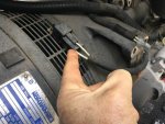
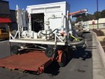
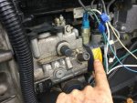
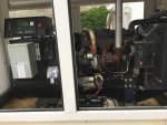
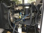
Through Ft Bragg GL, I bought this fuel pumping unit. It has a 60 kw civilian generator powered by a 4 cyl turbo diesel Perkins engine, 20 hp motor driving a fuel pump and associated electrical switches and panel. The control panel is a Deep Sea Electronics and it says the engine only has 112 hours since 2007. I am familiar with MEP generators (I own 4, 002,003,804a,804b) but have never run a large civilian generator. I found some information online for the control panel and engine. I connected a second battery to the electric fuel pump and solenoids on the injector pump (IP) since this was the only way I could devise to prime the engine. The fuel tank was not present so a jerry can is a temporary replacement. Fuel circulates and returns to the tank. The problem is that fuel is not going from the black manifold with the yellow sticker on the IP out to the injectors at the cylinders no matter how much I run the fuel pump. The are two electric solenoids on the IP, the upper seems to stop fuel flow for shutdown while the lower one seems to be a safety if the coolant temperature gets too high, both work when powered by the second battery while running the fuel pump. Any suggestions are welcome. I bought this unit to power a large compressor and blast cabinet.
 

Attachments

NDT

Well-known member
Steel Soldiers Supporter
10,163
5,844
113
Location
Camp Wood/LC, TX
You do not mention cranking the engine. If the IP does not turn via cranking the engine, no fuel will go to the injectors.
 

Guyfang

Moderator
Staff member
Moderator
15,878
22,111
113
Location
Burgkunstadt, Germany
Indeed, you need manuals, badly. I have never seen one like this. But let's see if we can't clear up a few things. You can crank the engine? It's got good fuel. Normally, fuel, air and compression is all that's needed to run. You have air, I assume compression is there, so that leaves fuel. Your fuel system appears to work, so we come to what will not allow the fuel to enter the IP. Is there a "fault indicator", or something similar to that on the set? When you opened it up for the first time, did it appear that anything was missing? Hacked into? Any sign someone had "fixed it". Any wires just hanging loose?

Most of newer power generation sets have a Motional Sencer. Or better known as a Magnetic Pickup. Since you have several TQG's, you should know what I am talking about. If the Mag Pickup is not adjusted properly, no signal will go to the solinoid, (from the govenor)on the IP to allow it to open. This is one idea to keep in mind.

If there is any Safty circuit problems at all, it will also cut fuel off to the IP.

You have "jumped" several components, with a hot wire, but is the path to ground good. If the path to ground is through another component, that dosnt work, or hasn't been energized, that it's not going to let your hot wired component work.
 

robertsears1

Active member
255
118
43
Location
Near Apex/NC
Thanks for the suggestions. Probably the most likely is that whatever turns the IP has sheared off. It looks like I will need to remove the radiator and that plate in the first picture to get to the mounting bolts for the IP. If it has, getting it timed correctly may be a challenge. I did find an operating and maintenance manual by Perkins but it is rather light on detail. This unit does have some kind of block that may be a magnetic pickup but I thought since I was holding the shutoff solenoid open with the second battery, that feature had been nullified.
Robert
 

Attachments

Guyfang

Moderator
Staff member
Moderator
15,878
22,111
113
Location
Burgkunstadt, Germany
Right above you thumb, are two spade connectors. Just what are they for?

I have exactly once, in my life seen a drive unit fail for an IP. I think you need to go back to looking for an electrical problem.
 

robertsears1

Active member
255
118
43
Location
Near Apex/NC
Not sure what they are for. There are a couple more places for connections around the engine also. I am getting on the trail for a detailed shop manual. I would love for it not to be a drive issue for the IP. The IP only has the two solenoids going to it and I believe I have accounted for their operation. I had toyed with the notion of removing the stop solenoid and putting a short bolt or stopper to remove that variable although then I have to stop the engine if it fires, perhaps blocking off the air intake.

Robert
 

snowtrac nome

Well-known member
1,674
137
63
Location
western alaska
most of the newer perkins engines have a drive gear bolted to the pump hub, the holes in the gear are elongated to allow timing, the gear is accessed through a hole behind the water pump, there is usually a hole in the gear and hub you stick a 3/8 rod or drill bit in to find tdc. Likely the gear and shaft are spinning its a pretty robust set up more likely a pump internal problem or something with the fuel shut off device.
 

snowtrac nome

Well-known member
1,674
137
63
Location
western alaska
I should also add that pump looks different from the old perkins engines, or any of the new electronic engines, I have worked on, It might be one of the transition engines. The basic block and lay out looks like the new engines, but the pump is way different, and may be a generator specific pump with some kind of electronic internal governor.
 

robertsears1

Active member
255
118
43
Location
Near Apex/NC
Best I can tell, this is a RG 1104 engine. The tag (which is very hard to get to and read) says this is a RG51236. It also has 2442/1800 but unable to find what that correlates to. Still trying to find detailed information. The IP has Delphi cast on the side. The tag on IP says Perkins type 1438 des 9320A312T.
 

robertsears1

Active member
255
118
43
Location
Near Apex/NC
I have found a service manual online for this series 1100 engine. This is a 1104 with a Delphi DP210 series IP which is self bleeding. I will be on trips the next two days with lots of waiting so I will have time to gather information. I have learned that the top solenoid is indeed the stop solenoid but the lower solenoid is the cold start advance unit. All it said to do to remove air from the injector pump is to run the fuel pump three minutes of which I have done several times. I will study more.

Robert
 
Last edited:

snowtrac nome

Well-known member
1,674
137
63
Location
western alaska
yes it is a 1100 series engine, the ones I have worked on have an electronicly controlled stanadine pump. I have never seen one with a Delphi pump, so I cant tell you much about them, I can say to acess the drive gear the water pump will have to come off, and 1/4 drive universal joint sockets are a must have to get the back nuts off, just got through doing one on a cat it 28 with the same engine but different pump.
 
Top
AdBlock Detected

We get it, advertisements are annoying!

Sure, ad-blocking software does a great job at blocking ads, but it also blocks useful features of our website like our supporting vendors. Their ads help keep Steel Soldiers going. Please consider disabling your ad blockers for the site. Thanks!

I've Disabled AdBlock
No Thanks