• Steel Soldiers now has a few new forums, read more about it at: New Munitions Forums!

  • Microsoft MSN, Live, Hotmail, Outlook email users may not be receiving emails. We are working to resolve this issue. Please add support@steelsoldiers.com to your trusted contacts.


701a hooking up to a 30amp camper

helomedic1171

Member
205
12
18
Location
Dacula, GA
Me again -

I'm trying to use my 701a to run 120/1ph so I can get all 30+ amps on one leg. The goal is to be able to run my 30amp camper from it as needed; I've even got an RV receptacle and some cable I can run to the lugs on the 701a so it looks all fancy and is easy to use.

Using this thread as a guide:

I deduced that I had the "ground safety modification" on my unit to run it in 240/120 split 1ph, and I need to change something(s) in order to do what I'm attempting.

Currently, I have a wire going from the L0 inside my control box to the frame GND Lug on the unit.

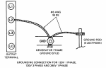
I have removed it from the L0 and moved it to the L2 in order to run 120/1ph, and per the TM-12, will then run a ground wire/cable to my ground rod.

I'm using 8ga (or maybe 6ga? Can't tell) cable for my power cable. There are 3 (red, blk, wht) power wires and 3 ground wires (all green). I'm unsure what to do with the green wires - I understand they are ground, but do I just twist them together and bond them to the frame somewhere nearby? Or do a pigtail and send the one tail down to the GND lug on the frame with the L2 GND cable? Or do I simply hook these to L2 as well since they're all grounds?

At the other end will be my RV receptacle to plug in the camper.

As of now, I'm planning to use :

Red-> L1 for power
Blk-> L2 for neutral
Wht (not used)
Grn -> ??? (Do I hook these to frame ground?)

The end goal is to have 30+amps (120/1ph) to run a camper using an RV receptacle at the end of this cable.
 
Last edited:

Zed254

Well-known member
866
465
63
Location
S. Hampton Roads, VA
The TM for the M E P - 0 1 6 B indicates you have an Output Selection switch that allows you to select 120V 1 Phase output. I don't own one so have no idea of the differences in your 701A. TM has a wiring diagram that may help: https://www.steelsoldiers.com/threa...-to-work-on-the-mep-701a-and-mep-016b.172682/

MARINE CORPS TM 05926B/06509B-12
ARMY TM 5-6115-615-12
NAVY NAVFAC P-8-646-12
AIR FORCE TO 35C2-3-386-31
(3)
(4)
Refer to Table 4-7 and use a multimeter to check the continuity of the
switch contacts for each position on the switch. Continuity will be
indicated when terminals are connected.
Replace switch if continuity requirements are not met.
Table 4-7. Voltage Reconnection Switch Connections.
Position ...................................Contacts Closed
120/208V 3 Phase .................1-2 5-6 7-8 9-10 17-18
120V 3 Phase......................... 1-2 3-4 11-12 13-14 19-20
240V 1 Phase......................... 3-4 9-10 21-22 None None
120V 1 Phase ..........................3-4 11-12 13-14 15-16 23-24
 

helomedic1171

Member
205
12
18
Location
Dacula, GA
Yes.

Not mentioned is that nearly all of the 701a units (016B with an ASK installed) have a "ground safety modification" performed where a wire is run from the backside (control box side) of the L0 to the backside of the frame GND lug to run in std 240/120 "household" voltage.

I changed that back to run 120/1ph, and I have seen the diagram in the -12 on grounding L2->GND->GNDrod which I've included here, but what I'm asking is what to do with the bare/green ground wires in my cable. On the receptacle end, they will go to the ground screw on the receptacle box. But on the generator end, do they still go to GND at the ground lug, anywhere on the frame, or to L2?
 

Attachments

Zed254

Well-known member
866
465
63
Location
S. Hampton Roads, VA
I power my 120V 30 amp camper with an 802: WAY too much power so I need to have a couple extra heaters working. I did not rewire ANYthing in my control box. I simply used my Output Selection switch and dialed in 120V single Phase. I have the Neutral and Ground bonded with a driven ground rod because it is a stand alone power unit .

I do not understand the need to rewire your control box.

Edit: removed pics of MEP-803
 
Last edited:

Zed254

Well-known member
866
465
63
Location
S. Hampton Roads, VA

Coug

Well-known member
Steel Soldiers Supporter
2,842
4,067
113
Location
Olympia/WA
Ground wires go to the ground lug. They shouldn't ever go anywhere else.

Their purpose is to equalize voltage on all exterior surfaces and give electricity an easy path to escape back to ground/earth in case power tries to go someplace it isn't supposed to.

The L0-ground wire you moved to L2 is there to bond the two circuits together because ultimately no matter what path the power takes, it needs to go back to where it started. Bonding produces a low resistance path that will help the breaker to trip due to overload, where if it had to take a longer path there is often enough resistance to keep the breaker from tripping and prolonging the fault in the circuit. This creates a shock/electrocution hazard if a living entity, be it human or animal, inserts themselves into the circuit creating a lower resistance path.
 

Zed254

Well-known member
866
465
63
Location
S. Hampton Roads, VA
Coug: for this machine (701A) in 120V single phase....is
L1 = Hot
L2 = Neutral
The L2 bonded to Ground
L3 and L0 not used
???

TM for 701A shows.....
a. Models MEP-016B and MEP-021B. Refer to Figure 4-1 and connect the load
cables to the generator set as described below. Be sure that the output
selection switch (located inside the control box) corresponds to the load
terminal connections.
(1) For 120 volts, single phase; connect cables to terminals L1 and L2.
(2) For 240 volts ,single phase; connect cables to terminals L1 and L2.
(3) For 120 volts, three phase; connect cables to terminals L1, L2, and L3.
(4) For 120/208 volts, three phase, four wire; connect L1, L2, and L3.
 

helomedic1171

Member
205
12
18
Location
Dacula, GA
I power my 120V 30 amp camper with an 802: WAY too much power so I need to have a couple extra heaters working. I did not rewire ANYthing in my control box. I simply used my Output Selection switch and dialed in 120V single Phase. I have the Neutral and Ground bonded with a driven ground rod because it is a stand alone power unit .

I do not understand the need to rewire your control box.
The 701a is a different unit than the TQG series. It was not intended, as delivered, to run 240/120 single phase supply. They were commonly altered at the unit level to do that, and when you run them in 120/1ph, you have to change that wire back. The commonly held theory is because when run in this manner, you have to be more careful with load balancing and are at risk of overloading the machine because you only run 15+amps x2 legs vs 30+ amps on one leg. With the 240/1ph setting, you're supposed to be running a 240v device and not splitting the load, hence the change in the wire to L0 as the neutral lug and bonded to GND.

I plan to run it as designed and intended on 120/1ph because my 30amp camper doesn't need 240v at all.

2 phase power is a misnomer - it only exists in PA, mainly in the Philadelphia area, and may have finally been decommissioned though I'm not certain about that. It may still be in use for all I know. Everywhere else runs 1ph or 3ph power depending on zoning and power requirements. Residential is nearly always 1ph, but runs 240v at the main via two separate 120v legs... Hence "split phase" though it's still just 1ph, either 120v or 240v.

You did answer my question, though - I need to bond the ground to the frame because the camper is NOT grounded like a house is, and thus would be dependent on the generator for proper grounding.

I'll be switching cables - this 6ga stranded is too heavy for what I'm doing and a short (less than 10') run of 10/2 UF-B will do fine for what I'm planning.

I also picked up a 10' run of 10ga stranded cable in green insulation for my ground cable from the Genset to the rod.

VERY helpful. I sometimes confuse automotive/DC vs home wiring colors when I don't have both in front of me, so this was a good reference. Thank you.
 
Last edited:

helomedic1171

Member
205
12
18
Location
Dacula, GA
Ground wires go to the ground lug. They shouldn't ever go anywhere else.

Their purpose is to equalize voltage on all exterior surfaces and give electricity an easy path to escape back to ground/earth in case power tries to go someplace it isn't supposed to.

The L0-ground wire you moved to L2 is there to bond the two circuits together because ultimately no matter what path the power takes, it needs to go back to where it started. Bonding produces a low resistance path that will help the breaker to trip due to overload, where if it had to take a longer path there is often enough resistance to keep the breaker from tripping and prolonging the fault in the circuit. This creates a shock/electrocution hazard if a living entity, be it human or animal, inserts themselves into the circuit creating a lower resistance path.
This makes a lot of sense. Thanks for explaining it more in-depth to me. Safety is important to me, and I don't want someone/thing becoming an extraneous GND.
 
Top
AdBlock Detected

We get it, advertisements are annoying!

Sure, ad-blocking software does a great job at blocking ads, but it also blocks useful features of our website like our supporting vendors. Their ads help keep Steel Soldiers going. Please consider disabling your ad blockers for the site. Thanks!

I've Disabled AdBlock
No Thanks