• Steel Soldiers now has a few new forums, read more about it at: New Munitions Forums!

  • Microsoft MSN, Live, Hotmail, Outlook email users may not be receiving emails. We are working to resolve this issue. Please add support@steelsoldiers.com to your trusted contacts.


.

74M35A2

Well-known member
4,145
312
83
Location
Livonia, MI
I don't think so. Measuring today. It is not a forward mounted shift type trans case, so fingers crossed.

Picked up a new pilot bearing, clutch brake, and alignment tool for the 2"-10 spline trans input shaft. Slight debate on clutch with the counter guy, so not in hands yet.

IMG_1849.jpg
 

Bandit02

New member
199
3
0
Location
Blind Bay, BC
Dont need the alignment tool, the plastic ones are't precise.

If your mounting the clutch up put it on the imput shaft of the trans, then you don't need to wrestle with alignment, just line up the holes with bellhousing and bolt those on first then the clutch to the flywheel.

If you wanna stab it instead which can take forever, take the shaft off the trans and use that as a alignment tool. It's 6 bolts for the cover plate and a snap ring that holds it into the bearing.

My reason for not stabbing is if there is one burr on the shaft it'll never stab and/or the release bearing can get stuck not letting you engage or disengage, same with the clutch plates gettting stuck.

If you put them on the shaft first you can also positively make sure the clutch plates arent in backwards (there's writing on them telling you what side they should face the pressure plates, at least on the Eatons), Put one of those in wrong and it's slip slip slip.
 
Last edited:

74M35A2

Well-known member
4,145
312
83
Location
Livonia, MI
Intetesting, thanks.

Just went all in, and bought the single most expensive part, the new clutch. At this point, the only major piece I see needing is a new output drive yolk on the trans rear to match U joint styles.

IMG_1852.jpgIMG_1850.jpgIMG_1855.jpgIMG_1853.jpg
 

74M35A2

Well-known member
4,145
312
83
Location
Livonia, MI
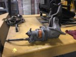
Used hydraulic slave and release fork arrived. Confirmed it fits the clutch housing properly. This one has an air assist on it (Wabco gen II), so you can feed it regulated air pressure to ease clutch pedal pressure. I also have a non-assisted slave if that somehow works better, was $25 on eBay to try.

Air Fork.JPG Fork Bell.JPG

Next step, test run the engine, and jamb all this together.
 

74M35A2

Well-known member
4,145
312
83
Location
Livonia, MI
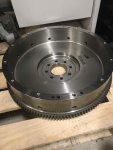
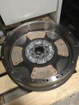
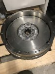
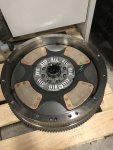
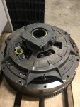
Assembly sequence of dual plate cup style flywheel/clutch:

IMG_1864.jpg IMG_1865.jpg IMG_1866.jpg IMG_1867.jpg IMG_1869.jpg

This style is very rare today, most use a traditional flat flywheel. I needed to use this to achieve the required torque holding capacity in an SAE #2 configuration (14" clutch), as not wanting to change rear motor mount type/locations unless mandatory. Not pictured are 6 drive pins which the center platter is keyed to, yet allowed to float when released.
 
Last edited:

74M35A2

Well-known member
4,145
312
83
Location
Livonia, MI
Measured up from the underside. The Roadranger trans is 38.5" from mounting flange to output flange U-joint centerline. While under the truck, the Allison appears to measure about 38". Could I be lucky enough to not even need to mod the slip splined prop shaft going to the T-case?

Also, the shift lever measures 17" back from the same mount flange face. This puts it at flat floor pan area, several inches back from where the floor pan makes its up angle heading toward the pedals and firewall. Puts it right about where the auto shift tower is, but that needs to go anyway. Looks like no gooseneck in the stick, or a slight rear one, followed by a slight angle bend rearward, and we should be good to go.

Is this really just going to drop in and work this easily?
 
Last edited:

red

Active member
1,988
22
38
Location
Eagle Mountain/Utah
Best Eddie Murphy voice: "I toll'd you".
Agreed.

Not quite a drop in, but much simpler than many people keep making it out to be. Remember the medium/heavy duty truck market is like big legos, it's designed to be mostly interchangeable. The exact opposite of the 1 ton and lighter market where most stuff is unique to each vehicle.
 

74M35A2

Well-known member
4,145
312
83
Location
Livonia, MI
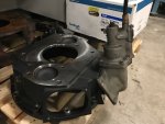
Latest concern, flywheel housing. Cummins online seems to indicate the flywheel housing which mates to the MT654CR auto trans is "extra deep". This would likely prevent me from using it directly to mate to the 13 speed Road Ranger trans. I do have 2 traditional flywheel housings, of which one is linked to a 6 speed manual, but their side mounts may be a different pattern or location. That still could work with some changes, maybe.

Open homework item. Go home and measure depth of stock mil 8.3L flywheel housing. The ISL/Allison 3000 and 8.3L/6 speed manual flywheel housings I have for reference both measure up at 5.25" deep. Also could possibly mill the stock mil one down if only need to go a little and it leaves enough thick material remaining. I would support the rear of the trans is I had to do it this way. Hoping it is not extra deep (even though it seems to be).
 

wcuhillbilly

Member
421
4
18
Location
Devils Tower, WY
If I was closer I would offer to take the eaton 6spd off your hands for extra $$ to toss at the tranny swap... need a 6406 or 8406 OD Eaton to replace the 2nd NV4500 in my Daily Driver in my sig....

Looking forward to seeing this OTR tranny project come to life, torn between a Eaton 10spd or a 13spd 9513 that I have laying here for the M816 Wrecker.

(Where did that popcorn eating smily run off to)
 

Jbulach

Well-known member
Steel Soldiers Supporter
2,593
2,055
113
Location
Sunman Indiana
If I was closer I would offer to take the eaton 6spd off your hands for extra $$ to toss at the tranny swap... need a 6406 or 8406 OD Eaton to replace the 2nd NV4500 in my Daily Driver in my sig....

Looking forward to seeing this OTR tranny project come to life, torn between a Eaton 10spd or a 13spd 9513 that I have laying here for the M816 Wrecker.

(Where did that popcorn eating smily run off to)
Ssshhh.... ixnay on the opcornPay ilysmay, they are watching!!!
 

74M35A2

Well-known member
4,145
312
83
Location
Livonia, MI
Interest in the 8.3L core engine and 6 speed manual trans is much lower than I anticipated. I'll just be taking them in for scrap next weekend. Can't even get $100 for either of them.
 

gringeltaube

Staff Member
Super Moderator
Moderator
Steel Soldiers Supporter
6,885
2,267
113
Location
Montevideo/Uruguay
.................
Open homework item. Go home and measure depth of stock mil 8.3L flywheel housing. The ISL/Allison 3000 and 8.3L/6 speed manual flywheel housings I have for reference both measure up at 5.25" deep. Also could possibly mill the stock mil one down if only need to go a little and it leaves enough thick material remaining. I would support the rear of the trans is I had to do it this way. Hoping it is not extra deep (even though it seems to be).
You probably know it by now: your MT654 housing is in fact 6.50 inches deep; just confirmed.
And yes, there is plenty of material on the transmission side, but if you removed more than 3/4" you'd soon fall into the pocket for the fording plug. And more than 1" would start compromising the housing structure, IMHO.
After 1-1/4", the wall section tapers outward (inner diameter increases; wall gets thinner). So, if you wanted to (re)use the same mounting bolts and deepen the 12 holes accordingly, the bottom end of these holes would be open to the inside of housing, leaving the bolt threads partially exposed. Not very elegant, I guess...
 

tobyS

Well-known member
4,820
815
113
Location
IN
Interest in the 8.3L core engine and 6 speed manual trans is much lower than I anticipated. I'll just be taking them in for scrap next weekend. Can't even get $100 for either of them.
Sorry to catch just the end, but will you give me the story of the 8.3 condition and tranny condition?
 

74M35A2

Well-known member
4,145
312
83
Location
Livonia, MI
You probably know it by now: your MT654 housing is in fact 6.50 inches deep; just confirmed.
And yes, there is plenty of material on the transmission side, but if you removed more than 3/4" you'd soon fall into the pocket for the fording plug. And more than 1" would start compromising the housing structure, IMHO.
After 1-1/4", the wall section tapers outward (inner diameter increases; wall gets thinner). So, if you wanted to (re)use the same mounting bolts and deepen the 12 holes accordingly, the bottom end of these holes would be open to the inside of housing, leaving the bolt threads partially exposed. Not very elegant, I guess...
Thanks for checking. I'm going to make an attempt to compare motor mount hole locations with the other 2 flywheel housings I have. They may be comparable, or easily adaptable if I can re-drill or shift the bushings in the mount up/down.
 

74M35A2

Well-known member
4,145
312
83
Location
Livonia, MI
Getting ready to pull the 13 speed out of the storage rack, degrease it, and pull the clutch housing off. Will reseal the input shaft while it is out, and update the range selector valve to the latest revision.
 
Top
AdBlock Detected

We get it, advertisements are annoying!

Sure, ad-blocking software does a great job at blocking ads, but it also blocks useful features of our website like our supporting vendors. Their ads help keep Steel Soldiers going. Please consider disabling your ad blockers for the site. Thanks!

I've Disabled AdBlock
No Thanks