• Steel Soldiers now has a few new forums, read more about it at: New Munitions Forums!

  • Microsoft MSN, Live, Hotmail, Outlook email users may not be receiving emails. We are working to resolve this issue. Please add support@steelsoldiers.com to your trusted contacts.

802/803A Quad Wiring

moarheavyduty

New member
Steel Soldiers Supporter
10
19
3
Location
Richmond, Virginia
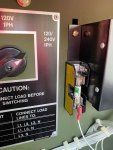
I am working on a new to me 2009 802A that seems to have an issue with the Quad Wiring Circuit going into the A1 VR. It has the Fuse Mod installed and it's shown on the circuit diagram inside the driver's side door so I assume it was built this way. Usually, there is ~69 VAC on the Q1 & Q2 going into the A1 and normal power output as expected.

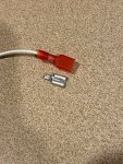
Occasionally, the machine has started with very low power ouput of only ~20-30 VAC which doesn't even move the Voltage gauge except when starting with S1 in Start position and full power output is shown. As soon as S1 released back to Run position the voltage drops down. When this was happening, I noticed there was zero voltage on the Q1 and Q2 leads. When I tested the resistance the circuit was Open / High.

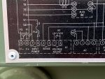
I read there is a separate AC output from the genset to run the A1 which is different from the main 5kw Load Output. Where in the Genset does the separate Quad Circuit AC output come from? In the TM I have seen it reference the main AC stator but never found details of the generator assembly. I was wondering if the smaller stator in the back cover of the genset is what generates the separate AC for the voltage regulator?

Thanks for your help!
 

kloppk

Well-known member
Steel Soldiers Supporter
1,980
3,103
113
Location
Pepperell, Massachusetts
Yes, the Quad winding is part of the main Stator windings. The Quad winding is what provides the ~69 VAC to power the A1 VR.
I'd suggest checking the wires where they exit the gen head. I've encountered a few sets where one of the wires from the Quad winding have been broken there. Next check the contacts in P5/J5. The Quad output power to A1 and the Field power from A1 go thru that connector.
 

zarathustra

Active member
Steel Soldiers Supporter
235
58
28
Location
glasgow,ky
The machine is designed to generate a small AC voltage even if the regulator is not connected (or fuse removed). That's your 20 - 30 volts. What that tells you is the unit can generate AC. When you manually "flash" the generator (S1 in start) and the AC goes up to the correct voltage then that tells you the unit is capable of generating the full AC .
.
So..... since the unit is making 240 vAC when being flashed, but the AC drops to the 20-30 v range when S1 is in RUN, there has to be something wrong with the control electrics as opposed to the generation electrics. I'd start with the fuse mod circuitry.
 

moarheavyduty

New member
Steel Soldiers Supporter
10
19
3
Location
Richmond, Virginia
Thanks kloppk and zarathustra. The generator has been running/starting OK for the last couple of days so I don't know how often this is a problem. I have been checking the wiring and it all looks good and like new. From behind the control panel at A1 down through J5 and into main generator case. The Q1 & Q2 quad AC + Field wires are easy to trace since they are different wire type and bundled separately from the rest of the heavier connections going into the gen.

Is there a diagram that shows the internal generator wiring? What connects to #13?

Thanks for your help


kloppk

Well-known member
Steel Soldiers Supporter
1,980
3,103
113
Location
Pepperell, Massachusetts
No diagram that I know of for the stator. It's just the 6 power windings and the Quad winding.
#13 is essentially a Zip tie.
The leads of the Exciter have female spade lugs on them. They get connected to #10. Then the two Exciter wires from the head are also connected to #10.
 

zarathustra

Active member
Steel Soldiers Supporter
235
58
28
Location
glasgow,ky
# 11.... That's part of the voltage control. It takes varying DC input from the voltage regulator (varies due to load) and creates a field which in turn creates an AC signal in the rotator as the rotor turns. That AC signal is converted to DC inside the rotor (see rotating diodes) and in turn passes that signal to the main field (part no 39 above). As that rotates it generates AC voltage in the stator (part 47) which is effectively the output of the generator.

The reason for going from DC to AC to DC for the controls is that the generator is brushless and ya gotta get the voltage regulator DC signal into the rotor somehow.
 

moarheavyduty

New member
Steel Soldiers Supporter
10
19
3
Location
Richmond, Virginia
Thanks for your replies! The explanation for the controls operation is very helpful. I started the generator this morning and the problem is back again: no voltage across the Quad wiring going into the A1 which of course means no power output. It has been starting and operated normally since I started this thread almost two weeks ago. I haven't run it much but started a handful of times to see if Voltage would come/stay up.

Visually Inspected all the wiring for this circuit going into the main generator again and it all looks nice and clean. Perhaps I am missing it in the TM but can't find much info to troubleshoot further. Been looking at your replacement VR as well, Kloppk.

Is it common for the Quad AC voltage to be an intermittent problem? My impression was this was more of an "all or nothing" kind of thing but I really don't know. Appreciate any advice and suggestions.

Thanks
 

moarheavyduty

New member
Steel Soldiers Supporter
10
19
3
Location
Richmond, Virginia
I think this problem is fixed now and I'll share what happened in case it helps someone else down the road. On my last post, I figured out this was an intermittent problem, coming and going with no obvious cause. Usually, the generator would Start and Run fine but often times the voltage meter would drop to zero after starting up which was result of whether or not there was ~70VAC at the A1 input. This machine was built in 2009 and seems to have come from the factory with the Fuse Mod already installed. It's shown on the door panel diagrams, with the Fuse "FU2" in-line with the Q1 lead going into Pin #8 on the A1 voltage regulator, as expected.

With the problem narrowed down to the Quad section, I went back to double check resistance between Q1 & Q2 (which should be roughly somewhere between 0.9 and 1.6 ohms according to the TM, depending on if it's an 802A or 803A). I was seeing many hundreds of ohms and sometimes an Open circuit. On my initial cursory inspection, this just seemed consistent with main stator out of spec for high resistance. On the second go-round, I used a set of alligator clips on my meter and pretty quickly found that physically moving the wire bundle behind the panel around would cause the readings to change drastically. It was more difficult than I anticipated to trace whether the problem was with the Q1 or Q2 wire but finally narrowed it down to the short jumper wire running from the #8 pin on the A1 regulator to the top of the Fuse Mod holder (Q1).

This jumper wire was folded back on itself in the harness and I figured it must be the problem. As I was disconnecting the wire from the fuse block, the connector just came off with no resistance. The metal female spade was broken inside the rigid plastic insulation on the connector. Looking more closely, it seems the wire wasn't stripped enough or was not inserted far enough when it was crimped. Regardless, with the jumper wire fixed I am getting a consistent 1.4 ohms measurement on the leads and power output as expected.

Fingers crossed... :unsure:
 

Attachments

Top
AdBlock Detected

We get it, advertisements are annoying!

Sure, ad-blocking software does a great job at blocking ads, but it also blocks useful features of our website like our supporting vendors. Their ads help keep Steel Soldiers going. Please consider disabling your ad blockers for the site. Thanks!

I've Disabled AdBlock
No Thanks