• Steel Soldiers now has a few new forums, read more about it at: New Munitions Forums!

  • Microsoft MSN, Live, Hotmail, Outlook email users may not be receiving emails. We are working to resolve this issue. Please add support@steelsoldiers.com to your trusted contacts.


803 Bogs Down and dies at 85% Load

USAMilRet

Member
392
15
18
Location
Tampa, Florida
Cummins does not sell nor has heard of diesel break in oil and again recommended the Valvoline Premium Blue.

Catapillar parts sales has never heard of diesel break in oil.

I called both service rebuild centers in Tampa and Riverview.

Cummins says:

Valvoline Premium Blue Oil

Valvoline's Premium Blue Engine Oils are designed to provide advanced lubricant performance in modern, emissions treatment equipped diesel engines, including all types of Exhaust Gas Recirculation (EGR) and Diesel Particulate Filters (DPF).
When used in conjunction with Ultra-Low Diesel Sulfur fuel, this product technology offers a long-life, extended drainage capability, balanced formulation which helps maximize engine durability and after-treatment cleanliness.

Valvoline's Premium Blue Engine Oil is endorsed by Cummins and has been tested extensively by Cummins in stationary and EGR on-road engines, including engines powered by diesel, CNG, LNG, as well as engines equipped with DPFs. It is tested and approved against industry standard specifications such as SAE, TMC and CES.
Additional product benefits include:

  • Unique dispersive polymer technology (DPT), with premium Group II base oil, provides advanced soot control, and cold start protection
  • Valvetrain wear protection and reduced oil filter restriction at high soot levels
  • High temperature deposit control, including single and two-piece pistons, and ring/liner wear protection
  • Higher TBN level and TBN retention for long-life performance, while meeting all chemical limits
To learn more about Valvoline's Premium Blue Oils available for Cummins engines, please contact your nearest Cummins Sales and Service location.
 
Last edited:

USAMilRet

Member
392
15
18
Location
Tampa, Florida
Yeah.....found some finally. Some JD break in oil for diesel engines. Another obstacle overcome.


Need to adjust the stop screws on the lever, fuel, run/stop. According to the TM need a gauge 317-50115. Is there a way to adjust the stops without the gauge and be accurate enough?

Neither the stop nuts or bolts are tight and are just rotating due to vibrations. Suggestions?
 

Guyfang

Moderator
Staff member
Moderator
15,919
22,227
113
Location
Burgkunstadt, Germany
If you would download all the documents in the MEP-803A file, in the TM section, there is a document falsely named Fuel injection pump procedure. Read it.
 

Guyfang

Moderator
Staff member
Moderator
15,919
22,227
113
Location
Burgkunstadt, Germany
The document should be call Engine stop screw adjustment. If I was working on these things, I just might take a look at every document in the file. You can learn a lot by reading.
 

USAMilRet

Member
392
15
18
Location
Tampa, Florida
Again....I have downloaded all the docs and have READ the too.

Simple question.....is there a way to set the stop without the gauge. A quick down and dirty. Like years ago we used a matchbook cover as a feeler gauge for plugs and points.....yes, points.
 

Guyfang

Moderator
Staff member
Moderator
15,919
22,227
113
Location
Burgkunstadt, Germany
Read the first page. It has no mention of the gauge. You can make the gauge. I think the measurements for it are in the Engine TM.
 
Last edited:

USAMilRet

Member
392
15
18
Location
Tampa, Florida
Is this associated with the fuel solenoid?
Yes. There are two stops for the fuel stop/run cam/lever. One at the top to limit CCW rotation, and one at the bottom that limits CW rotation. The cam is attached to the fuel rail that positions the fuel metering pumps. The fuel rack is also attached to the govenor system, it is actually a part of it.

Based on the cam position, that sets the rack position for fuel flow and fuel cutoff. So if the stops are not set properly, the generator can either starve for fuel, have it cut off, or have regulated flow via the governor system. The outside of the cam is attached to the fuel solenoid in the lower of the two upper holes, although various (at least 3) diagrams in the TMs show it attached to any of the 3 holes.
 

USAMilRet

Member
392
15
18
Location
Tampa, Florida
3-23.5. Adjustment.a. Adjust governor lever (6, FIGURE 3-19) assembly end play as follows:(1) Move lever assembly (6) until it abuts against top pivot support (9). Check that it falls freely under its ownweight.(2) Check governor lever (6) assembly end play. Add or remove 0.0098 in. (0.25 mm) shims (11), at toppivot support (9) to obtain an end play of 0.0039 to 0.0118 in. (0.1 to 0.33 mm).NOTEAdjustments in steps b thru d must be done with gear end cover installed.b. Adjust control lever (25) setting as follows:(1) Turn control lever (25) counterclockwise into stop position.(2) Adjust upper capscrew (17) until it just touches curved part of lever (25) and lock it in this position with nut(16).(3) Move lever (25) clockwise to run position and make appropriate 'G' setting.c. Make governor 'G', setting as follows:NOTEThe 'G' setting is made to ensure that fuel pumps deliver correct amount of fuel for desired enginespeed.

NOTEThis adjustment requires use of governor setting gage (317-50115).

(1) Move lever (25) clockwise to run position.(2) Insert 26.5 part of setting gage between head of upper capscrew (17) and top of curved part of lever (25).(3) Adjust lower capscrew (17) until lever (25) just touches setting gage.(4) Tighten lower capscrew locknut (16).(5) Remove gage.

NOTESpeed adjustment must be made with engine installed. Refer to end item maintenancemanual.NOTESpeed adjustments are made after governor has been correctly set. Capscrews (35 and 36) areused to adjust speed control.NOTEEngine speed is controlled by speeder spring (1) inside crankcase.d. Adjust speed in accordance with end item maintenance manual.

From the DN4M TM9.....24.PDF
 

DieselAddict

Well-known member
Steel Soldiers Supporter
2,483
1,884
113
Location
Efland, NC
Here are my thoughts. This obviously isn't the recommended procedure but this is how we used to check the injector pump setup on old diesel tractors.

1. Install a hydraulic pressure gauge on the outlet of one of the fuel injector pumps. Make sure you have a valve to bleed off the pressure. Alternatively you can disconnect the injector lines and look for flow.
2. Spin the engine over starting with the fuel lever in the cutoff position. If you get fuel pressure (or fuel flow from injector pumps), adjust cut-off stop until you don't.
3. Reassemble and test shutdown function.
4. Profit
 

justacitizen

Active member
408
40
28
Location
oklahoma
if i understand correctly. the engine stop lever opens or closes the fuel rack either completely closed shutting off the fuel or completely open to allow the governor to either open or close fuel sleeves in the pumps via the rack to maintain RPM and load. if the fuel cut off lever is mis adjusted to not allow full travel of the rack as the governor calls for more speed or fuel to maintain speed and load the result would be loss of power and speed at high demand. if the demand or load continued to stay or increase the engine would bog down and die under load.
 

USAMilRet

Member
392
15
18
Location
Tampa, Florida
So todays work consisted of finishing up things that needed to be done. I filled with clean diesel. Could not find any off road diesel place for fuel. The one I knew was down for pump replacement. So I paid $3 gal. Air filter is new. Oil filter is new. Oil is 15w30 JD Diesel Break in Oil with the addition of Lucas engine break in oil additive. Fuel filter is new.

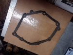
The front seal was replaced to end a minor oil leak. In the Army, it would have put it out of service. There was no gasket between the gear end cover or the crankcase. Just some RTV cement. So I made a gasket for it. I checked the govenor system and following the directions listed above, got absolutely NOWHERE with the first sentence because the rack #6 is not even close to #9 pivot pin so how it shuts is beyond me. Then there was the issue of the .004 in clearance of what is again beyond me.

Things looked normal with no signs of anything wrong. I was even able to visualize the fuel metering pin from the first injector pump being moved by the fuel rack.

Radiator was partially emptied and I'll be cleaned with a flush additive to it.

I need a new fanbelt. Not critical but beginning to show some deterioration.

After reassembly of everything, fuel system was bled of air and genset was started. Started right up. Oil pressure now at 50psi so my "unauthorized" adjustment of elongating the relief valve spring to increase relief pressure worked. It went from 7 psi to 50 psi at startup by that fix. No visible exhaust after startup but I could smell the sulfur additive from the Lucas additive, or maybe from the JD oil. Ran it to operating temp while checking for leaks then shutdown with no issues except the missing fuel run/stop solenoid.

So now I need to hook up my load bank and put a 100% load on it and run it hard to get things seated right.

More pictures to come later.....
 

USAMilRet

Member
392
15
18
Location
Tampa, Florida
if i understand correctly. the engine stop lever opens or closes the fuel rack either completely closed shutting off the fuel or completely open to allow the governor to either open or close fuel sleeves in the pumps via the rack to maintain RPM and load. if the fuel cut off lever is mis adjusted to not allow full travel of the rack as the governor calls for more speed or fuel to maintain speed and load the result would be loss of power and speed at high demand. if the demand or load continued to stay or increase the engine would bog down and die under load.
I thought the same thing but once the governor system takes over the fuel rack placement based on demand, the position of the fuel stop/run lever is of no concern except to overide the governor for shutdown.

At least that is what I think after examination of the governor fuel rack interface.
 

USAMilRet

Member
392
15
18
Location
Tampa, Florida
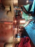
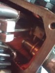
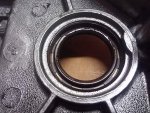
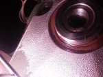
Some pics of todays works. Seal, fuel rack, gasket, etc...

Behind the front gear cover:

20180726_200555.jpg20180726_200605.jpg20180726_200652.jpg


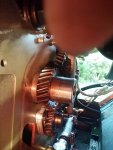
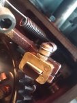
Notice the end of the fuel rack in the upper right hand corner...the square block....


20180726_200703.jpg

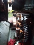
Fuel rack

20180726_200711.jpg


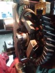
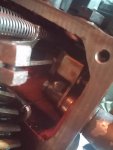
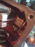
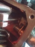
Fuel rack in various positions while turning the lever, fuel, stop/run on the outside of the crankcase.

20180726_200908.jpg20180726_200911.jpg20180726_200916.jpg20180726_200920.jpg
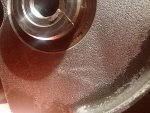
Leaking seal
20180726_210209.jpg

Why the seal was leaking. Note the scarring. Just enough to make it necessary to replace it.

20180727_203147.jpg

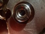
New seal installed:
20180726_214511.jpg20180726_214508.jpg20180726_214424.jpg20180726_214416.jpg

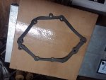
New home made gasket for gear cover....

20180726_210321.jpg20180726_210315.jpg
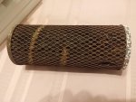
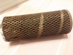
Original Donaldson air filter. Probably has been in the machine since it's original build.

20180727_202913.jpg20180727_202859.jpg
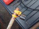
Home made specialty tool to help with those nasty nuts. Especially the middle one on the top of the radiator. Who designed this stuff?????
20180727_170838(1).jpg
 

USAMilRet

Member
392
15
18
Location
Tampa, Florida
Did you check the cracking pressure before and after cleaning it? Did it change?
Now that the oil pressure issue is resolved.....went from 7psi to 50psi with my spring adjustment in the relief valve.......I can check for crankcase vacuum in the AM when I put it on the load bank. Will check the fuel pressure while running also.
 

Guyfang

Moderator
Staff member
Moderator
15,919
22,227
113
Location
Burgkunstadt, Germany
What type of problem?

Compression problem. Rings not seated right. Not installed properly. Thai kind of thing. Use the oil dip stick hole, as the oil filler tube is too wide/big.
I'll use a vacuum gauge.
you can, or build a manometer. It's simple, easy and the TM explains how. The quick and dirty method is simply a small piece of paper. Since I needed one all the time, I took an extra oil fill cap, drilled a hole through it and inserted a brass fitting. Sealed it with epoxy, and hooked up my hose to it. Overkill for you, unless you are going into a new line of work.
 

Daybreak

2 Star Admiral
Steel Soldiers Supporter
1,521
741
113
Location
Va
Howdy,

A Onan DN_M (Lister-Petter LPW_) engine is sloppy precision. It is not spec'd like a new current engine. The design itself is now over 30 years old. Break in oil is just that. Non detergent oil with additives for the proper mating of metal to metal surfaces.

I was under the impression you said all filters were new? That air filter has issues.
 
Last edited:

USAMilRet

Member
392
15
18
Location
Tampa, Florida
Howdy,

A Onan DN_M (Lister-Petter LPW_) engine is sloppy precision. It is not spec'd like a new current engine. The design itself is now over 30 years old. Break in oil is just that. Non detergent oil with additives for the proper mating of metal to metal surfaces.

I was under the impression you said all filters were new? That air filter has issues.
I was told all filters were new. The oil and fuel filter were obviously new so I assumed (bad thing to do) that the air was changed as well as was told. But apparently in the haste to get me the genset (as it had been 9 months) it appears some minor things were overlooked like the air filter, the disconnected temp overheat switch, break in oil (never used by builder) and a few other minor things.

Not to fear, I changed all the filters and that included a new air filter. And you may be right, that the air filter may be a cause (chocked for air) but they say that the air cleaner was not attached when testing so he did not feel that this was an issue.

In reference to the oil, break in or not, the parts guy at Cumins Diesel said that he went out on to the floor and spoke with his mechanics that have been doing this for 30 years and they have never heard or used any type of break in oil in any diesel rebuild. Of course they know of it for gas engines, but never for diesel. He called me back two hours later and told me that.

Everyone is speculating that the reason the military uses it so extensively is because of the PCMS and the daily, weekly and monthly first echelon maintenance in the military services. It HAS to be done. The guys at JD told me that unless otherwise specified, they will not use break in oil because the customer does not want to be bothered with changing oil and filter so soon, or anything time after that for that matter.
 
Top
AdBlock Detected

We get it, advertisements are annoying!

Sure, ad-blocking software does a great job at blocking ads, but it also blocks useful features of our website like our supporting vendors. Their ads help keep Steel Soldiers going. Please consider disabling your ad blockers for the site. Thanks!

I've Disabled AdBlock
No Thanks