• Steel Soldiers now has a few new forums, read more about it at: New Munitions Forums!

  • Microsoft MSN, Live, Hotmail, Outlook email users may not be receiving emails. We are working to resolve this issue. Please add support@steelsoldiers.com to your trusted contacts.


Air Dryer for an M35A2

Valence

Well-known member
Steel Soldiers Supporter
2,135
612
113
Location
Davis County, UT
I believe that I was told it was a brand new unit. And for the price (~$250 shipped), I sure hope it is. Though I'm not sure if I can trust my memory! Hah.
 

rustystud

Well-known member
9,071
2,388
113
Location
Woodinville, Washington
004.jpg005.jpg006.jpg007.jpg To take the spitter valve apart, you must first find a 1/8" or 3/16" thick piece of steel a little over 1' wide. Put this in a vise tightly. Then set the valve on it aligning it up with the 2 notches on the piston (pics 3-4 ) . Then pushing down firmly on the valve use a 3/8" socket and remove the top bolt. To reassemble just reverse the procedure.
 

brianp454

Member
572
11
18
Location
Portland, OR
I know this thread is a bit old, but I'm looking into this again.

Yes, it is common to use something like silicone grease in manufacturing for assembling o-rings. You just want to use a lubricant that is not the same base as the o-ring material as it will break the o-ring down in no time.

Did you ever get your issues worked out?

Finally pulled this off my air dryer. All 3 o-rings are there, but it is also covered in what appears to be dialectic grease too? I thought that was odd.

View attachment 576998 View attachment 576999 View attachment 576997 View attachment 576996
 

Valence

Well-known member
Steel Soldiers Supporter
2,135
612
113
Location
Davis County, UT
I know this thread is a bit old, but I'm looking into this again.

Yes, it is common to use something like silicone grease in manufacturing for assembling o-rings. You just want to use a lubricant that is not the same base as the o-ring material as it will break the o-ring down in no time.

Did you ever get your issues worked out?
Thanks brianp454!

I have not worked on this issue since these posts last year. Recently though, I've had this air dryer on my mind. I'm still not sure what the problem is, but I bet it is something that I have or have not done. But I need to look for that square o-ring rustystud mentions above.

As I've been thinking about the air dryer on and off for almost the past year, I was wondering if it would operate better once I hooked up power. I was also wondering that since I've replaced the air compressor on my truck with one with less than 2000 miles on it, if the air dryer might work better. My original air compressor seemed to generate a lot of blow-by out the slobber tube (crankcase breather tube) and was noisier during operation.

If neither electrical power nor my newer air compressor solved the issue, I was considering taking the truck to some medium duty truck service center (or any place that services trucks with air brakes) and may haps see what they can figure out on the air dryer.
 
Last edited:

brianp454

Member
572
11
18
Location
Portland, OR
Thanks Valence! I’m trying to get some things sorted out myself.

I’m working on installing this and the brake switch upgrade (moves the switch from the high pressure line to the brake pressure line for the trailer circuit). I got the switch kit from Erik’s (Brake Light Air Operated Switch Upgrade Kit For M35A2, 12255668 after my SECOND switch failed in a year. Sick of that crap!

So for installing the AD-9, does anyone have a clear before and after set of schematics showing how to hook it up?

So for installing the brake switch upgrade, does anyone have the TM or detailed setup for how to do so?
 

The King Machine

Active member
396
91
28
Location
Vancouver, British Columbia
I tapped the main line from the compressor along the frame rail. Plumbed it into the dryer, then out to the accumulator tanks. I took power from the wire heading into the lift pump in the fuel tank. Added an inline fuse. Bolted the dryer to the outside frame rail. Was very easy about a 2 hour job, do yourself a favor and grab some plug and play DOT air fittings and plastic line. As I make repairs to the air system I am replacing all the copper lines with plastic.

The brake switch was really straight forward also. The kit from Eriks was what I used and comes complete with everything you need. Took me about 20 min I'll take a picture after work.
 

Attachments

Valence

Well-known member
Steel Soldiers Supporter
2,135
612
113
Location
Davis County, UT
Thanks Valence! I’m trying to get some things sorted out myself.

So for installing the AD-9, does anyone have a clear before and after set of schematics showing how to hook it up?
You're welcome!

Did you see the schematic and other pictures/description I posted back on post #88? What I did was interrupt the supply line to the air tanks (from the air compressor) and route over to and through the air dryer and then back to the air tank's inlet. And then in post #90 for tapping off the control line on the governor over to the air dryer.


I’m working on installing this and the brake switch upgrade (moves the switch from the high pressure line to the brake pressure line for the trailer circuit). I got the switch kit from Erik’s (Brake Light Air Operated Switch Upgrade Kit For M35A2, 12255668 after my SECOND switch failed in a year. Sick of that crap!

So for installing the brake switch upgrade, does anyone have the TM or detailed setup for how to do so?
Ah, so you still had the brake switch on the brake fluid side?

Maybe my post and pictures here will help. In the pictures you can see where on the air pack the air brake switch is located, and if you follow the link in the post, you can see pictures of the older style "hydraulic" brake switch - which is what Erik's kit is the upgrade/replacement for.
http://www.steelsoldiers.com/showth...brake-switch&p=1881770&viewfull=1#post1881770
 
Last edited:

Valence

Well-known member
Steel Soldiers Supporter
2,135
612
113
Location
Davis County, UT
In my supplemental electrical air compressor installation, I decided it was time to revive trying to get my air drier to work, but this time I'm going to actually power the electrical connection. I've replaced the big, black (and expensive! :( ) hoses that I used once and instead I am using 3/8" poly air-brake line with push to connect fittings. This is already a MUCH cleaner solution.

2017-03-25 18.17.24.jpg 2017-03-25 18.17.05.jpg 2017-03-26 17.54.33.jpg 2017-03-26 17.54.53.jpg 2017-03-26 17.55.09.jpg

The added bolts for the wire clamps were only just barely accessible in that location. The clamps weren't big enough to use the existing air tank mounting bolts, so I mocked it up to make sure I could reach a bolt head with a wrench inside the C-shaped bracket. Word of warning, those upside-down C-shapes are excellent dirt holders, so doubly ensure you're wearing eye protection as debris falls on you. I suppose dirt in the face is kind of standard for working under any vehicle, really.

The 24v air compressors came with a 7-port 3/8" manifold (3/8" internal and end fittings, 1/4" face fittings). Both of the electric and the engine air compressor feed into the manifold, which then runs to the air drier "supply" port, and then from the air drier "delivery" back to the tank. Even though the air routing is slightly more complicated, the manifold is awesome. Maybe a 1/2" manifold would have been better, but we're only talking about 10-11 CFM here.

2017-03-26 16.52.27.jpg

The manifold ports are filled as follows (left to right):
  • (left end) hose for quick disconnect fitting
  • 165 PSI safety relief (there's now 3 safety reliefs in the system: one each on the tanks, drier, and manifold)
  • from rear Extreme Aire compressor
  • none (plugged)
  • from front Extreme Aire compressor
  • from engine air compressor
  • (right end) to air drier
 
Last edited:

silverstate55

Unemployable
Steel Soldiers Supporter
2,068
855
113
Location
UT
I've completed the new air brake hose routing to the air drier from the manifold. For added protection, I've covered each of the hoses in plastic split-loom.
You might want to reconsider the plastic split-loom over the electrical pig-tail where it rubs against the frame; instead, take some old fuel/oil/air hose and cut it to slip over that spot to better prevent the frame from rubbing through. That plastic split-loom won't last long with the Deuce vibrations while driving.

I only throw away old hoses if they are crumbling and falling apart as I hold them; instead, I keep them in a bin to use as insulation & protective wrap for other hoses/wire looms.
 

Valence

Well-known member
Steel Soldiers Supporter
2,135
612
113
Location
Davis County, UT
You might want to reconsider the plastic split-loom over the electrical pig-tail where it rubs against the frame; instead, take some old fuel/oil/air hose and cut it to slip over that spot to better prevent the frame from rubbing through. That plastic split-loom won't last long with the Deuce vibrations while driving.

I only throw away old hoses if they are crumbling and falling apart as I hold them; instead, I keep them in a bin to use as insulation & protective wrap for other hoses/wire looms.
There's actually two layers of split loom there, 3/8" and 1/2". But you're right, a piece of hose would provide better protection.
 

nchittendon

Active member
544
28
28
Location
La Crosse, Wisconsin
Yup, after my main harness caught fire, and I spent an afternoon with a test light and multimeter, the repair ended up being covered with a hose I cut down one side AS WELL AS split loom on top of it. Now every place I could find with wire possibly touching metal it got a piece of hose wrapped around it.
 

Valence

Well-known member
Steel Soldiers Supporter
2,135
612
113
Location
Davis County, UT
So I thought this time the air dryer would behave differently, but it doesn't appear so.

1. It doesn't sound like the engine mounted air compressor ever turns off, even though system pressure is just above 120 PSI. Like adding the control line from the air governor to the air dryer interferes with the governor somehow.
2. And since the air compressor never shuts off, or the governor is perhaps behaving weird, the air dryer vents periodically with strange ~30 seconds of not fully closing after a purge.

I took a two minute video showing the cycle. The soapy water you see on the air dryer was my doing, looking for leaks.

https://youtu.be/G8Kd_nEMXxE

This photo showed where I tapped into the air governor for the air dryer control line. The hard line below runs to the top of the air compressor.

image.jpg image.jpg

Does the stock M35A2 control line form a vacuum instead of pressure? (I don't know how it works).
 
Last edited:

rustystud

Well-known member
9,071
2,388
113
Location
Woodinville, Washington
First off the main line to the AD9 should be 1/2" not 3/8" line. It should come from your wet tank not straight from the compressor. Second the 1/4" line to the governor is pressure not vacuum. Did you use the same line (pressure hole) on the governor that should have come from the air tank to connect the AD9 to ? There should only be two lines coming off the governor. One should be from the AD9, and the second goes to the air-compressor. I can see from your photo you have the governor installed wrong. You must eliminate that old copper line and install the AD9 line to that plug. Second the air-compressor line should only be one line straight from the governor to air-compressor. The way it is installed now, everytime the AD9 burps it shuts-off the air-compressor for a moment. Then when the burp is over the air-compressor comes back on. The poor air-compressor is going crazy !!!
 
Last edited:

Valence

Well-known member
Steel Soldiers Supporter
2,135
612
113
Location
Davis County, UT
First off the main line to the AD9 should be 1/2" not 3/8" line. It should come from your wet tank not straight from the compressor. Second the 1/4" line to the governor is pressure not vacuum. Did you use the same line (pressure hole) on the governor that should have come from the air tank to connect the AD9 to ? There should only be two lines coming off the governor. One should be from the AD9, and the second goes to the air-compressor. I can see from your photo you have the governor installed wrong. You must eliminate that old copper line and install the AD9 line to that plug. Second the air-compressor line should only be one line straight from the governor to air-compressor. The way it is installed now, everytime the AD9 burps it shuts-off the air-compressor for a moment. Then when the burp is over the air-compressor comes back on. The poor air-compressor is going crazy !!!
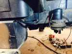
Rusty, I'm sorry I don't follow all of your connection description. I have plumbed the air dryer according to the instructions, as posted in Post #88, which definitely shows the dryer being placed before the air tanks and the only portion of the AD-9 connected to the governor is the "Control" line. I don't see it being of any help for the AD9 to run its delivery line over to the governor first then down to the air tanks. Are you saying this figure is wrong?
2015-08-01 11.14.24.jpg

In my post just yesterday, there are only two connections on the air governor. The small copper line out the bottom runs to the air compressor, and I assumed that was the unloader port referenced in the above instructions. I tee'd off from that with the 1/4" poly line to the "Control" port on the dryer.

image.jpg

A friend did some Google searching for me and found other's with my exact, same issue:
https://www.bigmacktrucks.com/topic/22364-air-system-purging-too-much-from-the-dryer/
"... I have replaced every major component and it stll wants to build up to 130 psi then purge until psi drops to 110 or so then the purge valve shuts off and the cycle repeats. one note if I pull the feed line from the governor to purge valve it will stop purging any ideas what going on with this? thanks for any input"

I wish the post included pictures, but one fellow claims this was solved by:
"I had the same problem with the AD9. On the side of the dryer there is a half inch plug, take it out. Inside you will see a plastic X shaped pin, take it out. There is a spring attached to it. on the other end should be a small O ring. Mine was gone. Replace this O ring . Problem solved. PS I couldn't find one so I made one. from a rubber washer."
 
Last edited:
Top
AdBlock Detected

We get it, advertisements are annoying!

Sure, ad-blocking software does a great job at blocking ads, but it also blocks useful features of our website like our supporting vendors. Their ads help keep Steel Soldiers going. Please consider disabling your ad blockers for the site. Thanks!

I've Disabled AdBlock
No Thanks