- 640
- 942
- 93
- Location
- Texas Hill Country
Well for 'only' 8x the cost we dropped in a Leece Neville 24v 200a unit. It required modifying the J180 bracket, though used the existing serpentine. Our intended loads add up to more amperage than yours, though I like the small form pad mount unit you have and the thriftiness. Admirable work! I am feeling like a spendthrift.I figured I'd post the progress here instead of the starter thread, since others may look here first for alt options.
I got the delco-Remy aftermarket alt today and mocked it up with some 3/8 studs. I don't have any 4" long 3/8 bolts but I'll get them tomorrow. See photos. The unit fits perfectly in that mount with space behind. Seems peachy. My old pulley fits right on there. The shipping box had a test report in it. Says 130a max output. for $170, I'm hoping this'll be reliable. 110a is the nominal rating at 24v
The belt is obviously long. I measured a 4.5" closer pulley position from the old pulley centerline with the tensioner at half position. So that's 9" shorter belt I need.
the parts spreadsheet says the 3126 has a 78.25" long k8 belt. I wonder if Napa will have the shorter one. More research..
anyway, we'll see tomorrow if the hot test works. This delco Remy is a brush type alt and single voltage which accounts for the smaller size. Probably not as mil spec as the neihoff but I just need simplicity.
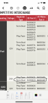
With the LBCD, battery disconnect relays removed and the Victron 24/12 70a mounted under the PDP supplying 12v to X3 we are seeing good voltage and little draw (0.05a).
Before starting at X1 and X3


After starting


We did findg a 200a alternator with a similar diameter to the Niehoff dual 100a (7" to 8"). No issue with the shock tower.


Since you also pulled your LBCD: Are you adding a voltage sensor to keep the 'Charging System' dash light operable?
Last edited:
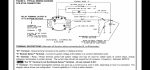
") ). Thats the beauty of remote sense, it takes the line resistance/voltage drop at the batteries when feeding current to the them, out of the equation by sensing the batt voltage on a separate line without any current flow on it… The reg on this alt will also drive a small relay or control a ignition powered dash warning light. The 28SI is on my short list for a replacement When my 100A Neihoff fails as there are a ton of them in service all over the world. With the “usa made” knockoff/compatibles ~$180, it is an inexpensive alternative, but even the genuine Delco’s are only ~$400-600
). Thats the beauty of remote sense, it takes the line resistance/voltage drop at the batteries when feeding current to the them, out of the equation by sensing the batt voltage on a separate line without any current flow on it… The reg on this alt will also drive a small relay or control a ignition powered dash warning light. The 28SI is on my short list for a replacement When my 100A Neihoff fails as there are a ton of them in service all over the world. With the “usa made” knockoff/compatibles ~$180, it is an inexpensive alternative, but even the genuine Delco’s are only ~$400-600