• Steel Soldiers now has a few new forums, read more about it at: New Munitions Forums!

  • Microsoft MSN, Live, Hotmail, Outlook email users may not be receiving emails. We are working to resolve this issue. Please add support@steelsoldiers.com to your trusted contacts.

Alternator question

pacebm

Member
140
0
16
Location
Brewton, Alabama
MY 1009 has been converted to 12v by the Roscommon method. The passenger side alternator has been converted to a civilian 6.2L setup with brackets and an internally grounded standard civilian alternator. The alternator was not charging last week so I put a new one on it. It appears to me that the alternator they sold me is bad because it will not charge over 12.3 volts but they checked it at the parts store and said it was good. I have attached a picture of the wiring so I can explain my voltages:

Charging wire 12.3 volts
The key and voltage sense wires are original to the harness. Both show 11.8 volts. I am assuming the voltage drop is due to traveling thru the wiring harness.
Both batteries are 12.1 volts.
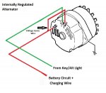
alternator-wiring.jpg
I'm looking for agreement that my alternator is bad or a suggestion as to why it will not charge over 12.3 volts. I was always taught that a working alternator should put out at least 13 volts. Correct me if I'm wrong.
 

Keith_J

Well-known member
3,657
1,315
113
Location
Schertz TX
The most likely issue is a burned out alternator light bulb. And that diagram is not correct because the sense wire should be connected to the battery. Very little current goes through the sense wire so the voltage on either end should be the same. But when the alternator is cranking out the current because the voltage is low on the sense line, there will be a big difference of voltage on the ends of the main output wire.

If I recall, the output wire on stock CUCV is # 6. At 70 amps of output, I measured a full 1/4 volt of difference. This is with stock Delco Remy 27 SI units.
 

Warthog

Moderator
Super Moderator
Steel Soldiers Supporter
13,775
227
63
Location
OKC, OK
Remove the two pin connector from the alternator and check the voltages with the key off and the key in the run position.

This is what you should be reading with the passenger side alternator with the correct Rosscommon 12v conversion.
Key off
red wire - 12v
brown wire - zero

Key on
red wire - 12v
brown wire - 12v

While your diagram will work it is not correct for a true Rosscommom conversion.

I would suspect that there is an issue with the GEN2 circuit. Bad bulb, bad fuse, bad relay or a bad diode.

Even though the GEN1 alternator is removed the GEN2 circuit must still be operational for the RC conversion to work properly.

Read the Alternator trouble shooting sticky and follow the GEN2 diagrams for the memtioned parts.
 
Last edited:

pacebm

Member
140
0
16
Location
Brewton, Alabama
I got another alternator but I'm still not charging. The diagram was used just for the purpose of showing what voltages I am getting and where.

Warthog -
The voltages all check out per your description; just a little less. Bulb and fuse are good but I will have to check the diode because I am not sure where it is located or how to check it. Off to the Alternator troubleshooting sticky.....
 

pacebm

Member
140
0
16
Location
Brewton, Alabama
The plug for the field and exciter wires was bad. Cut it off and used spades (new plug on order). Charging 12.5V at idle and 14V with some throttle. Should I be getting more volts at idle? I need to check if the pulley size is the same on a stock alternator versus this civilian version on the truck.
 

cpf240

Active member
1,479
5
38
Location
Free in Northern Idaho
Sounds like it is not charging at idle, and it should be charging. My guess would be that either your idle is low, or, more likely, the pulley is the wrong size, so the alternator is not spinning fast enough at idle. Just my thoughts, your mileage may vary.
 
Top