BlkH2O-Jarhead
New member
- 18
- 13
- 3
- Location
- New Mexico
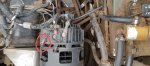
New alternator is in. I cannot remember where this one loose wire goes. Help please
Attachments
-
 1.8 MB Views: 23
Steel Soldiers now has a few new forums, read more about it at: New Munitions Forums!


Thank you
The loose wire should be 2A, dig all the silicone out (carefully) and look for the stud.Still not clear. The positive and ground are correct. The wires from the inside of the alternator are correct. They are shown on the diagram but on my alternator they are covered with a sealant. Still no indication of where the loose wire goes, shown in my photo. Open for advice. Thx
Until the gen starts working it can be no higher than battery voltage, did you test it with the gen connected? (to wire 56Yes. 568 shows 24v. Thank you for replying. Guys smarter than me said it should be more.